Hi, I am working on an adaptation to this circuit
http://www.instructables.com/files/orig/FX5/67GS/FLROK12R/FX567GSFLROK12R.gif
It is an LED vumeter that uses the lm386 and an electret mic to generate input to the LM3914 comparator/led driver chip. I used a much bigger capacitor (4.7 uf) at the input (let in more low frequencies into the lm386) .
I'm trying to insert active BPFs in between the 386 & 3914s in order to seperate the signal into its frequency content (i'm making an equalizer for a robot halloween costume!).
So I had some lm358 (shitty for audio, but 2 in a package) and followed this guide to make some BPFs.
Active Filter Calculator - Bandpass with OpAmp Designer in Javascript
For testing purposes I used two channels, fo = 35 Hz and fo =6 Khz, to illustrate some independant light movement (bass / high)
Something weird is happening : I think the signal is being shorted through the 358s to output unchanged.
I had tried connecting the filter stage to a seperate power supply to tinker around and noticed that the filter stage (on its on breadboard) was passing signals through without +9V supply.
I have a scope, it is shitty, but I really think both the output signals are nearly identical in frequency content.
K i think its working. But these amps are shitty and finicky. Maybe they'll work better on a proper PCB. Getting different vu meter readouts using different BPF outputs.
Been reading about this chip and it seems it will be a lot easier to implement ->
SparkFun Electronics - Graphic Equalizer Display Filter - MSGEQ7
The MSGEQ07 automatically splits audio into 7 frequency bins and provides a proportional DC output level based on the magnitude of the spectral power in said bins.
Has anyone done this? I hope there's a spot in the GTA where I can buy this chip. Ordering could take too long!
Can you post your EXACT circuit?
Concerning the filter stage: what you do with the "+" input of the op-amp needs some care.
Concerning the filter stage: what you do with the "+" input of the op-amp needs some care.
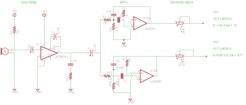
Hi, seems to work with these two bpfs based around the lm358. Shitty quality but i dont care about the fidelity of the audio, the chips are cheap and come 2x a package. Seems to drive the lm3914s niceley (not shown in schematic)
I plan on getting 10 of these in parallel, tapped from the c4 = 4.7 uF cap.
Is it reasonable to pick the R's & C's such that I get a small amount of gain in the signal (between 1.5-2, using Active Filter Calculator - Bandpass with OpAmp Designer in Javascript) and then use the sensitivity adjustment pots to bring the signal into the desired level??
I'm using parts that I have readily available. Going to pick up tons of caps/small valued resistors, odds and ends tommorow.
Here is a schematic --> suggestions welcome! I gotta get these boards built up the next 2 days...
Attachments
- Status
- Not open for further replies.