Opamp inverting input = GND
which means the circuit requires bipolar DC supplies like ±12V. In addition to the tube heater supply and the tube plate supply. Oh my!
And it's only available in one package, an SMD with belly solderpad. I'm sure that's the A-Number-One preference of guitar amp builders, worldwide. Oh my!
which means the circuit requires bipolar DC supplies like ±12V. In addition to the tube heater supply and the tube plate supply. Oh my!
And it's only available in one package, an SMD with belly solderpad. I'm sure that's the A-Number-One preference of guitar amp builders, worldwide. Oh my!

I'm sure that's the A-Number-One preference of guitar amp builders, worldwide. Oh my!
The pain, the pain, stuff copied off of old datasheets (including the useless parts) with no judgement or explanation.
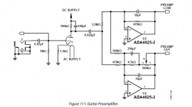
Add a couple of back to back zeners at the right arm of .022µF cap, to prevent damages to the IC at starting up /down, or cap failure.
Generally a good idea BUT in this case...
In the app notes says:
INPUT OVERVOLTAGE PROTECTION
The ADA4625-1 has internal protective circuitry that allows voltages as high as 0.2 V beyond the supplies to be applied at the input of either terminal without causing damage. For higher input voltages, a series resistor is necessary to limit the input current. Determine the resistor value by (VIN − VS)/RS ≤ 20 mA where: VIN is the input voltage. VS is the voltage of either V+ or V−. RS is the series resistor.
With resistor values shown these currents will be less than 1mA with a tube B+ of +400V.
Protection diodes not required.
Cheers,
Ian
Don't any of youse guys understand they did this in jest ?? -- much akin to Jim Williams using an LM317 as the error amplifier for a 75TH vacuum tube pass element.
Mbe there is a break-out movement within ADI to resurrect some of the LLTC mirthfulness.
I was talking about the other stuff, Jim called me years ago after LT copied some of my datasheet applications including the parts that did nothing and asked if they were there just to catch that. Of course I said yes, what else could I do? I could probably find out where that app came from, it is obviously tongue in cheek.
Last edited:
....stuff copied off of old datasheets...
I've read a lot of datasheets over the decades, and do not remember ever seeing this particular scheme. Maybe I missed it. But I think it is new, novel, and if you can define some I Claims even patentable. (Patents no longer have to be instantly "useful".)
Since when did DATA sheets become a platform for poor humor? Embarrassing........Don't any of youse guys understand they did this in jest ??
I've read a lot of datasheets over the decades, and do not remember ever seeing this particular scheme. Maybe I missed it. But I think it is new, novel, and if you can define some I Claims even patentable. (Patents no longer have to be instantly "useful".)
I meant the other applications, only I would notice this is very old stuff between Bill Gross, Jim Williams and me.
On a friday afternoon perhaps.
We often drove to the North End in Boston on Friday to go to The Daily Catch when it was still a few guys and electric frying pans each with our own bottle or six pack as we chose.
Since when did DATA sheets become a platform for poor humor? Embarrassing........
Have you ever read a User Manual for an HP Spec analyzer. As Janis sung, they "lay it between the lines."
Jim Williams ap-notes were chock-a-block full of humorous cartoons.
Have you ever read a User Manual for an HP Spec analyzer. As Janis sung, they "lay it between the lines."
Jim Williams ap-notes were chock-a-block full of humorous cartoons.
Tek had a Wizard 101 (W101) in their scope service manuals (Barrie Gilbert).
- Status
- This old topic is closed. If you want to reopen this topic, contact a moderator using the "Report Post" button.
- Home
- Live Sound
- Instruments and Amps
- Analog Devices Guitar Amplifier