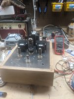
I started ordering parts 10 1/2 years and 2 houses ago. Now it's mostly mounted on a chunk of 3/16ths aluminum.
Jan 12AT7
Russian 7198 equivalents
Coke bottle 5U4
Hammond 272.....EX?
Hammond 20H choke
Trancendar OPTs. 5k:8Ohm
Next step is a plywood cradle for it to sit on during the build.
I'm going to do some sort of fancy wood frame upon completion.
I'm mounting the power cord and fuse on the base. I'll move the switch there if it seems to be a noise issue.
Ignore the plugs next to the power tubes. I realized I was probably going to burn myself using the volume knob and power switch. Makes for a sub-optimal listening experience. Live and learn. This is my first tube/valve chassis.
Hopefully people posting will guilt me into continuing progress!
Stay safe.
Last edited by a moderator:

OK, so I'll be watching - you betta getta move on! 😉
I have collected parts for a RH84 and am waiting on Chinese transformers, (!!). Edcor's shipping costs to the Antipodes are unbelievable!
Had mucho success with EL84s in a Tubelab Simple PP built point to point that I thought I'd like to try SE. Planning to use JAN 12AT7, 6P14P-EVs and 53CS (~5U4G) from Ukraine. My planned power supply PSUD is shown below - I'm hoping 3mV ripple is OK.
With B+ at 315V it's obviously version 2 of the RH84, but Beer30, are you building version 1?
Have fun!
Simon
Sorry to hijack the thread, but Simonism, highly suggest you revise your power supply. Way too much capacitance.
Also, what is the 3 ohm resistor for (R1)?
I did the same thing you did when I built my first amp: focus only on the ripple 10s of seconds after startup.
You need to look at the charge/discharge behavior of the circuit, too. This is referred to as the "time constant." Your huge amount of capacitance will translate to poor transient response.
Simply removing the second RC (85 Ohm - 560uF), you improve this dramatically. That will leave you with ~50mV ripple. (Don't forget that your output transformers will attenuate that somewhat.) In my experience, this is not a big deal, but you could improve it further with a choke with more than 4H inductance. Even 8H would be quite a bit better.
Personally I would use a constant current source in PSUD instead of a resistance, but maybe you know something I don't.
Attaching your original and modified circuit for illustration:

.png")
Also, what is the 3 ohm resistor for (R1)?
I did the same thing you did when I built my first amp: focus only on the ripple 10s of seconds after startup.
You need to look at the charge/discharge behavior of the circuit, too. This is referred to as the "time constant." Your huge amount of capacitance will translate to poor transient response.
Simply removing the second RC (85 Ohm - 560uF), you improve this dramatically. That will leave you with ~50mV ripple. (Don't forget that your output transformers will attenuate that somewhat.) In my experience, this is not a big deal, but you could improve it further with a choke with more than 4H inductance. Even 8H would be quite a bit better.
Personally I would use a constant current source in PSUD instead of a resistance, but maybe you know something I don't.
Attaching your original and modified circuit for illustration:
Hopefully people posting will guilt me into continuing progress!
Git-r-done. You'll have a nice sounding amp.
Mine from 10 years ago.
Attachments
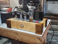
This will be a stunning looking amp. Lucky for you you’ve got some nice output transformers.I started ordering parts 10 1/2 years and 2 houses ago. Now it's mostly mounted on a chunk of 3/16ths aluminum.
Jan 12AT7
Russian 7198 equivalents
Coke bottle 5U4
Hammond 272.....EX?
Hammond 20H choke
Trancendar OPTs. 5k:8Ohm
Next step is a plywood cradle for it to sit on during the build.
I'm going to do some sort of fancy wood frame upon completion.
I'm mounting the power cord and fuse on the base. I'll move the switch there if it seems to be a noise issue.
Ignore the plugs next to the power tubes. I realized I was probably going to burn myself using the volume knob and power switch. Makes for a sub-optimal listening experience. Live and learn. This is my first tube/valve chassis.
Hopefully people posting will guilt me into continuing progress!
Stay safe.
View attachment 1225494
Thank you Thekak. I’ll read up on transient response, maybe here: Designing a PSU with DuncanAmps PSUD II by DHTROB
Simon
Simon
Update:
I built a simple plywood frame. It works.
Rectifier wired. 12AT7 half wire. Tube heaters wired with no ground faults. Pentode sockets are still pretty bare.
Large PS capacitor is mounted.
Shielded wire connected to RCAs and run to volume pot. It's a blue Alps(?) and is meant to be pcb mounted. I'm considering mounting it on proto-board to make soldering easier and more reliable.
I've got two solder lug strips mounted to the chassis for building the circuits. When I ordered OPTs, I got ultralinear taps. I left enough room between the solder lug strips to install two dpdt switches, I have all the components for V1 and V2 RH84s and am seriously considering switchable cathode resistor/ccs and UL taps/zener diode modes.
I'm not thrilled about my dual triode socket orientation. I should have wired it so my signal path doesn't have to go over my heater lines. Hopefully shielded wire will bail me out. This is my first scratch tube build. Live and learn. I would flip it around but I've already rewired the heaters once after I remember that 90 degrees is better for reducing noise and in this specific case, getting heater lines further away from low level signal. I'd rewire it again but I'm also worried my solder tabs might break from fatigue. I've got more sockets ordered. I'm going to run it how it is for now and see if noise is an issue. The practical experience is valuable.
I've got another solder lug strips I'm going to mount under the choke on which to build the power supply. I'm not sure how I feel about the adhoc nature of my power supply at the moment.
I wasn't sure where to put the chassis ground. I put a solder lug strips on one of the rectifier socket screws as a temporary ground point. I also used the lug strips to connect the heaters to the 6.3V tap off the PT. It was unplanned but I can't think of a good reason not to keep it. Of course I don't know much at this point.
There should be a variac on the way. I'm planning to use that to test my PS unloaded. My caps should be fine but I'd rather not replace them or the rectifier tube. Eddy Van Halen also said it will make my guitar amp sound cool!
i welcome any comments. Hope to have another update soon.
Thanks jgf. As far as I know, both of Alex Kitic's original and V.2 RH84 schematics show a single B+ line, so driver and output tubes are both on 300V with the original and 315V in the V.2 - the original with 47uF/20H choke/220uF and the V.2 (CLC version PS) with 47uF/10H choke/200uF. I proposed using a 560uF there in my noobiness chasing lower ripple. So I appreciate Thekak's input and do see how it makes the PS very slow, so I'm re-considering.
This is what I'm thinking about now (using parts that I already have) and it seems both reasonably fast with a 1 second ramp-up and ripple of 3mV:

The 3 ohm resistor was really there as a placeholder in case I needed to adjust the resulting B+, once I get my transformer into a circuit. The load as a resistance was just me playing around to see what the equivalent resistance of a constant 96mA load that I think my amp will draw.
Beer30 - please indicate if this hijacking of your thread is annoying you.
Simon
This is what I'm thinking about now (using parts that I already have) and it seems both reasonably fast with a 1 second ramp-up and ripple of 3mV:
Also, what is the 3 ohm resistor for (R1)? .....
Personally I would use a constant current source in PSUD instead of a resistance, but maybe you know something I don't.
The 3 ohm resistor was really there as a placeholder in case I needed to adjust the resulting B+, once I get my transformer into a circuit. The load as a resistance was just me playing around to see what the equivalent resistance of a constant 96mA load that I think my amp will draw.
Beer30 - please indicate if this hijacking of your thread is annoying you.
Simon
I can only find an RH84 v2 schematic: https://rh-amps.blogspot.com/2013/02/rh84-amplifier-revision-2_26.html, and it has an RC section in the power supply for the 12AT7. What I built was closer to v1, and I also have a supply for the input tube. Your supply in your last post looks like it should do the job well.
The charging speed of the capacitor should not affect the audio frequencies. As long as the power supply RC time constant, also quantifiable as the corner frequency, is below the audio range it should be good. Above that corner frequency, the signal passes through the capacitor.
The charging speed of the capacitor should not affect the audio frequencies. As long as the power supply RC time constant, also quantifiable as the corner frequency, is below the audio range it should be good. Above that corner frequency, the signal passes through the capacitor.
Why will capacitor value not affect transient response?
https://www.analog.com/en/analog-di...e constants,transient response of the circuit.
I know that solid state amplifiers tend to use enormous amounts of capacitance in their power supplies. But I am not familiar with why that is the case. But in my experience, with class A tube amplifiers not employing voltage regulation for the B+, properly designed PSU with carefully considered capacitance is crucial to good sound. On my first amplifier, I built it, listened a while, heard some PS ripple, and doubled capacitance in the final PSU capacitor. It was quieter, but it also sounded worse. That's how I got started on my PSUD journey.
I think you are just looking the initial charging time from 0 seconds, or power on. If you put a CCS as the ultimate load instead of a resistor, you can specify an instantaneous step change in the load and at what time in the sim it occurs. Choose the step time after the supply in the sim has reached equilibrium. This will be more like the transient response of the power supply. Then you can see if it makes a quick response with little ringing or has a lot of ringing. Many times in the sims I've done, there is more ringing with a larger inductor. You have to do some trial and error with values and topology.
Best of luck,
John
Best of luck,
John
The V.1 schematic can be found in this old post: https://www.diyaudio.com/community/threads/rh84-question.323355/#post-5502967

I simulated stepping the PS voltage using a stepped load of 120mA / 96mA and vice versa during (almost) stable operation after 1 second. I see no signs of instability or ringing going up or down. It may come to the point where I have to try something in practice to see what result I get.


I very much appreciate the discussion as I'm on a steep learning curve.
Simon
I simulated stepping the PS voltage using a stepped load of 120mA / 96mA and vice versa during (almost) stable operation after 1 second. I see no signs of instability or ringing going up or down. It may come to the point where I have to try something in practice to see what result I get.
I very much appreciate the discussion as I'm on a steep learning curve.
Simon
CLCLC seems overkill. I would breadboard a CLC with components at hand and see if it works well enough, and save the second choke for your next project. ymmv.

Hope I'm not threadjacking here.
It's actually been done for about 3 weeks or so. Work schedule and kids seem to come before internet posting.
Took about 40 minutes of me troubleshooting to find out I didn't have a fuse in it. Not my finest moment but relief when I figure it out.
I wish it was more exciting to write up but it just worked. I wired the volume pot wrong. More loud counter clockwise.
I thought it wasn't working because it didn't make any noise. Turns out, not a peep at full volume with no signal. I guess all the worry about 60Hz was wasted or paid off depending on your point of view.
No DC on the input; fed it some AC and out came music.
The whole event would have been anticlimactic if not for the glorious sound.
The screen switch between the ultralinear tap and 20v zener also works without issue.
I'd think I knew what I was doing if I knew I didn't know what I was doing. Hats off to the designer, Alex Kitic. I'm sure he'll this here. (cough)
I usually tinker with things well beyond the point of diminishing returns. Other than the UL switch, a 50uF (instead of 47uF, I'm a rebel) PS input cap, and a 200k bleed resistor, it's pretty v1.5ish stock. I'd planned all of those before I built it so it doesn't really count as tinkering. It sounds so good, I'm more interested in using it than messing with it. I wish I could do that with playing guitar.
I have rewired the pot in a more conventional clockwise louder manner.
Overall a very worthwhile build. I'd tell you what I learned from mistakes, but I didn't make any bad ones that I know about yet. The analytical part of me that enjoys troubleshooting is disappointed in a way. But, it sounds too good to care.
To first time builders:
1. Use those unused pins on sockets as extra solder lugs.
2. You don't realize you need more solder lugs until you run out and start looking for other things to solder to. See #1.
3. Careful planning of the chassis layout pays off. I wish I put even more effort into it. I didn't know I could.
4. Drill press not necessary but nice. Same for digital soldering station.
Time for some full range speakers to go with it.
Attachments
- Home
- Amplifiers
- Tubes / Valves
- An RH84 is half born