Hello,
I'm trying to build my own 5.1 amp and decided to use the TDA1554q for the satellite speakers I searched on for a pcb and found this(see attachments)
but I think it has too much capacitors and I'm afraid that this would screw up the sound please take a look and give your opinions.
I'm trying to build my own 5.1 amp and decided to use the TDA1554q for the satellite speakers I searched on for a pcb and found this(see attachments)
but I think it has too much capacitors and I'm afraid that this would screw up the sound please take a look and give your opinions.
Attachments
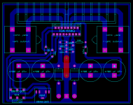
You can never have too many caps! What's going to screw up the sound in this layout is that you've not adopted star grounding. Notice that your input ground is not the same signal as going to the chip's power ground because there are some big caps between the two points. These caps couple noise from the +ve rail to the gnd.
Also I'd use SMT ceramics close to the chip, not leaded ones.
Otherwise looks fine - these are really excellent chips!
Also I'd use SMT ceramics close to the chip, not leaded ones.
Otherwise looks fine - these are really excellent chips!
You can never have too many caps! What's going to screw up the sound in this layout is that you've not adopted star grounding. Notice that your input ground is not the same signal as going to the chip's power ground because there are some big caps between the two points. These caps couple noise from the +ve rail to the gnd.
Also I'd use SMT ceramics close to the chip, not leaded ones.
Otherwise looks fine - these are really excellent chips!
Thanks for replying
could you explain a little more what do I need to modify in in order to make this circuit better cause I'm not at all familiar with "star grounding" also if you want take a look or use this pcb I've attached the layout file.

- Status
- Not open for further replies.