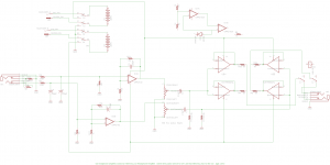
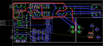
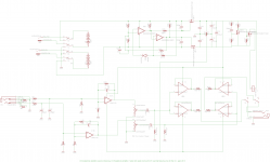
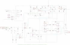
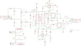
Here is another version of RocketScientist's O2, done purely for fun for DIY and not commercial. I'll call it an O3 for lack of a better name. This one fits in a Hammond 1455C1201 case Hammond Mfg. - Extruded Aluminum (Metal End Panels) - 1455 Series Enclosures, which is the "stretch" version of the case AMB uses for the mini^3 and is about 35% smaller, volumetrically, than the standard O2 B3-080 case. Even better the form factor is longer and narrow, more pocketable. BTW, I *love* AMB's mini^3!  I use mine all the time. Still one of the smallest headamps out there, and smaller than this will be.
Disclaimer: As much as I would like for this amp to be "objective", I don't have access to a dScope or Audio Precision tester so this amp will not be properly measured. Proper measurements are the whole point behind amps like the O2 and Wire, so for a properly measured amp don't build this! Get an O2 or Wire. This amp is just done for DIY fun using much of the same parts and design philosophy as RS did for the O2. I just wanted to see if I could wedge something like the O2 into a smaller case.
Some of the design goals:
* Lithium 600mAhr "9v" style (8.4V) batteries like this Rechargeable 9 Volt Lithium Ion Battery: BatteryMart.com. These have about 3 times the mAhr capapacity of the NiMH batteries in the O2.
* Does not include a charger (or AC supply, batteries only) and instead both batteries cable out to the manufacturer of the batteries own charger like this 2 Bank 9 Volt Battery Charger with 2 Li-Poly Batteries: BatteryMart.com, using 1mm DC power plug to 9V battery clip cables. Goes through a 4PDT switch to fully disconnect the batteries for charging. The manufacturer's charge is a 1.5 hour quick charger with proper charge controller chips.
* Since the O2 goes for about 8 hours on a charge, this should go for around 24 hours given the 3x battery capacity.
* Uses the SIP8 version of the NJM4556A chips to save space.
* Both through hole on the top of the PCB and surface mount under the PCB.
* Includes a mini relay to power the headphone jack. 2 seconds turn on delay and quick turn off on power off.
* Vertical 3.5mm switchcraft jacks to save space.
* No gain switch to save space. Just turn the volume control down.
* The 4PDT power switch is recessed at the rear to make the whole thing pocketable (switch won't accidentally turn on or off).
Negatives:
* These lithium batteries are only rated at about 100 charge cycles! That is right, $12 times two every 3 months if the unit is charged every day. Since the charge should last 24 hours that may be more like charging every 3 days, which would stretch it out to $12 x 2 every 9 months. From what I read people are using these lithiums in portable mics are are happy to pay the money in exchage for the vastly longer runtime.
* No gain switch.
* Batteries might be a tight fit, as with AMB's mini. The dimensions given by the battery manufacturer *should* work fine, with room to spare, but the reality may be different.
* SMD soldering, although I've kept it to the larger 1206.
* No on-board AC power supply, batteries only, so no way to "plug in" at work or home. But since the batteries store 3x the charge and last 24 hours, then charge in just 1.5 hours, probably won't be a big issue.
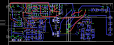
The PCB below is 20mm short and that will get fixed. Time to buy Eagle, lol! The PCB is 51.5mm x 120mm. The power managment circuit isn't finished yet since I'm probably going to upgrade it using the dual-section per-battery mod I posted a while back.
I'll post the Gerbers on the site here once I have it all worked out and tested. The gain stage will use the SSOP-8 version of the NJM2068 (Mouser has it now), I just haven't have a chance to add it to the Eagle library yet and grabbed the SMD OPA2132 for similar package and pinout.
Attachments
Last edited:
It fits! 
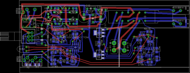
Below is the full 51mm (not 54mm, typo above) x 120mm PCB, including RocketScientist's power management circuit verbatim and my headphone output relay control circuit.
The parts have to stay 3.7mm away from the sides due to cover screw extrusions along the side in the box, but the traces can get within 2.2mm.
The SMD power mosfets don't need any significant heat sink foil since they always operate in switchmode.
Attachments
Here is a better charger idea for this project. The 4PDT switch can be wired to place the (NiMH now) "9V" batteries in parallel across a single DC jack, each in series with a resistor, exactly like the O2 amplifier's trickle charging setup. The charging adapter is just a common 12Vdc. Then in the other switch position the batteries are back to +/- with common ground. Kind of a slick way to convert a single-ended DC charger into a double-ended (albeit battery-only) power supply.
There is enough board space where two Lithium charge controller chips could be used instead of the resistors for Lithium "9v" cells, to make the charging on-board instead of external with two jacks. This simplifies things since there are a lot of chips out there for 2 isolated lithium cells in series, but charging with +/- common ground in place would be harder. This arrangement also disconnects the amp from the batteries - and the charger chips - during charging. The switch contacts won't all connect at the same instant when the amp is turned on, of course, but that is why the headphone output relay with the 2 second turn-on delay to make sure the power and chips are stable first.
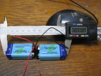
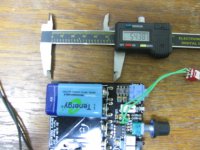
The batteries in this case will be an exact fit, as the photos below shows. Not enough room to use the O2's type of battery snaps. End to end the two cells are 103mm while the board has about 104mm of space. Maybe 105mm if I move the input jack up slightly.
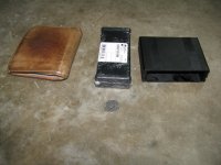
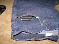
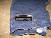
The next photo shows the O2's B2-080 case alongside the Hammond case and a wallet for size. The last photos show the Hammond case easily hides in a pocket. The case would slide in another inch or so, I just have it exposed for the photo. The O2 though kind of consumes the whole pocket.
I've included pads for resistors in series with the volume control feeds to add attenuation, if desired. I've found that I need about 12K with the 10K pot, slightly over 50% attenuation, with my various sources to keep the pot mid-range. Those pads can just have 0R jumper SMD resistors though to not use any attenuation. I've also added pads in the feedback loops of the NJM4556A's for 40K or 82K resistors to help cancel some of the input bias current induced DC offset. Those can also just be jumpered with 0R resistors.
Attachments
Last edited:
agdr
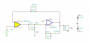
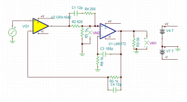
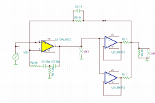
Can I suggest some changes to output stage, which with few extra passives will give you better linearity? It is sort of composite amplifier using opa1642+lm6172. It will also have quite low quiescent current, something like 8mA for both channels. For this reason I would also recommend to replace OPA2132(4) with OPA1642.
Can I suggest some changes to output stage, which with few extra passives will give you better linearity? It is sort of composite amplifier using opa1642+lm6172. It will also have quite low quiescent current, something like 8mA for both channels. For this reason I would also recommend to replace OPA2132(4) with OPA1642.
Last edited:
opa1642+lm6172
This is one of possible variants.
This way output stage will be within two feedback loops and at the same time we remove thermal feedback between output and input stage.
Both of those factors are promising more linear behavior.
Attachments
Hey guys, thanks for the comments and ideas!
I kind of lost interest in the O3 though after my last post in March due to learning about JDS labs C5 amp. The O3 benefit over the C5 would be larger mAhr batteries. I thought that there would be DC-DC converter noise remnants in the C5, but John Seaber sent me an FFT that shows no converter fundamental or harmonics making it into the audio. Pretty impressive.
I do hope that someone out there makes a DIY SMD O2 though, like those recent posts in the main O2 thread! Especially one with the DAC built in, although that would probably get into small SMD parts and production line type IR soldering.
availlyrics - I actually did use 2 of the SIP8 NJM4556ALs in the O3 for exactly that reason. I figured the SMD versions (M, V) would probably get too hot to deliver much power. I agree, running those SMD versions at low rail voltages would be the only real use for them. Still, like you say, in a small CMOY design that might do the job for a lot of high sensitivity IEMs or phones.
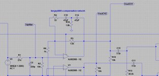
Sergey888 - good ideas for compensation! At one point several weeks ago I was thinking about using second order compensation on the ODA for a faster fall-off, when I was still using the LME49990 wrapped around the NJM4556AL buffers. But I couldn't find anything useful on the internet about second order compensation. So I tried rolling my own using a second order RC filter in the feedback loop but never could get it right in the simulation gain / phase results. I'll study what you have done here.
If you have any ideas for a second order compensation loop for the gain stage in the ODA please go ahead an post over in that thread. Right now it is the same thing RocketScientist / NwAvguy used, just the single 220pF across the 1.5k feedback resistor. A second order loop might be an interesting addition. It would probably have more phase shift, but that wouldn't matter anymore since the coupling caps are back in the middle of the ODA to isolate the grain stage from the output buffers.
Sorry for a horrible spelling in my previous post, it is so bad that it hurts 
Forgot to mentioned that you may need to use some simple clamping circuit in examples I've shown, to reduce transient during start up. I was using something like two anti-parallel diodes from input of the second op amp to the ground.
Forgot to mentioned that you may need to use some simple clamping circuit in examples I've shown, to reduce transient during start up. I was using something like two anti-parallel diodes from input of the second op amp to the ground.
Sergey888 - thanks, I really like your ideas. I'll take a better look this weekend and next week. Yeah I know you posted second order compensation there, 2 caps = 2 poles = 2nd order. My efforts didn't work but it looks like you have been able to get it working! I do like your idea of even faster roll-off.
In my view anything above 100kHz just has no place at all in an audio amplifier and can only result in trouble. I'm all for dropping the response of the amps above 100kHz to unity, or below, just as fast as possible.
In my view anything above 100kHz just has no place at all in an audio amplifier and can only result in trouble. I'm all for dropping the response of the amps above 100kHz to unity, or below, just as fast as possible.
agdr
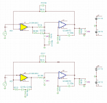
There is a general rule to make it working. It is required to return to 6dB roll off at least half decade before 0dB crossing. I usually do it a bit earlier, to have a bit larger phase margin.
Another thing that I would like propose you to consider is to go to inverting schematic. In case of non-inverting one there is a high chance that common mode induced distortion will dominate.
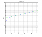
It may look awkward because of low input impedance of such amplifier will load potentiometer and you will get rather strange characteristic instead of exponential. But there is a trick you can use. If you load liner potentiometer with a resistance with is 10-20% of pot nominal value you will get rather good emulation of exponential characteristic. See pic below
Attachments
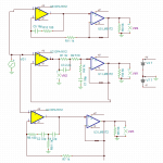
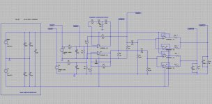
Sergey888 - I finally got some time to look over the circuits.  Your second order network at the bottom of the pictures in post 9 and 11 is the kind of circuit I was trying to get working but couldn't figure out. I see where I went wrong now. I had the feedback network as series R, C to ground, series R, and C to ground again. In yours the last two R and C are both in series.
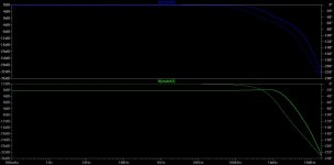
I've just applied your network to the input stage of the standard O2 amplifier and the LT Spice simulation results are interesting, below! I really like how your second order network rolls off faster and more linearly than the basic O2 220pF capacitor. The O2 starts rolling off at 100kHz though and your network is starting the roll-off at about 1mHz. Ideally I would to alter it to start rolling off at 100kHz - 250kHz or so. Or maybe not - as it is now the phase shift is totally flat to 30kHz which is great. If the gain rolled off sooner than 1mHz that would likely drag a tiny amount of phase shift below 20kHz.
With the standard O2 values, I think the first roll-off from 100kHz to about 5Mhz is probably just due to the compensation inside the chip itself, looking at the NJM2068 gain/phase plot on the datasheet. Then the feedback capacitor starts adding in around 5mHz, which is why the slope of the roll-off changes from 1st order to 2nd order at 5mHz.
I actually had suggested switching to two inverting stages to RocketScientist / NwAvGuy back in 2011. As I recall he acknowledged that it may be a tiny bit better but had a higher parts count and lower input impedance to the amp. I think there was some other issue that I'm forgetting now. I'll take another look at that.
The top plot in blue is the bottom half of the circuit, which is just the standard NwAvGuy O2 headphone amp values. The bottom plot in green is with your compensation network. Both plots are at the output of the first (gain) stage, not the output of the second buffer stage.
Attachments
Last edited:
agdr
You may be also interested to see open loop gain plots. They will give an idea about closed loop stability.
I've just noticed that you exclude output stage from the loop on DC ( i mean presence of C16, C11, R13, R14, R3 and R9), and the way it is designed output stage works more like a bootstrap than "traditional" buffer. While it is a bit more simple, it is inherently worse performer. I would recommend at least to consider to change this consent. At the end it will take even less passive components.
See example below
Attachments
Last edited:
Hey guys, thanks for the comments and ideas!
<snip>
I do hope that someone out there makes a DIY SMD O2 though, like those recent posts in the main O2 thread! Especially one with the DAC built in, although that would probably get into small SMD parts and production line type IR soldering.
<snip>
.
I actually had conversations with NwAvGuy about a surface mount version of the O2 in 2011 and he thought is would be a interesting project. I never released the board but I did not a layout of the O2 and substituted surface mount devices where possible. It ended up 1/3 through hole and 2/3 surface mount. The regulators, mosfets, opamps and a few other devices needed to remain through hole. It was a drop-in replacement for the O2.
Other than going blind soldering 0805 resistors there is no real advantage with this board.
It is not practical to create a DIY O2 + ODAC due the proprietary nature of the Tenor USB engine. You also have the soldering issues of working with 0603 components on the DAC. The majority of the builders would not have experience with components this small and it leave them with a bad taste in their mouth if the 'kit' could not be completed.
Manufacturers of USB audio engines guard their secrets jealously and prefer not to release chips and tools to the general pubic. To release the schematic for the ODAC I had to ask for and receive permission from Tenor. I was told that was an exception.
George Boudreau
Yoyodyne Consulting
George - that is some interesting O2 history! Thanks. 
Yeah once the space requirements for all the "unshrinkables" on the O2 are added up - jacks, pot, batteries, switches - the remaining circuitry doesn't add that much it seems.
I agree about the small (0805, 0603) SMD stuff for the same reason. Not DIY friendly, especially for the less experienced solderers. I think a lot of PCBs would just wind up on the shelf after folks tried to solder the first one. I've kept everything on the desktop unit 1206 for that reason. Then I read a slide presentation by Hoffer at AP saying they prefer 1206 thin film in low tempco, even over bulk metal foil due to LF AC distortion issues. Lol - how about that for dumb luck. There was actually a good electrical reason to go with it.
That is interesting about the proprietary nature of the digital parts. I haven't done digital design in a long time and am way out of date. I did run into that problem 15 or so years ago with some (analog) video chips from Philips. We all had to all sign NDAs and had to get the vendors involved in the project to sign to get any technical data on the parts. Even had to lock the documents in a safe overnight as part of the contract, as I recall. Can be really frustrating!
Well NwAvGuy/Rocket Scientist is/was a genius. Hopefully he will resurface some day.
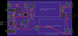
The O3 would fit in a Bud EX-4501 case
I've run across a way to fit this project into a case. I just learned about the Bud Industries line of extruded aluminum cases. It also looks like there is a new(er) generation of lithium polymer "9V" batts out with a 720mAhr rating:
2 Bank 9 Volt Battery Charger with 2 Batteries: BatteryMart.com
The amp section is just a "repaired" version of the National LME49600 datasheet headamp, using a LME49720HA (TO-99 can) dual op amp, two BUF634's heatsinked to the front panel instead of LME49600s, and two OP177 DC precision op amps for the servo. Using the OP177's it will zero out the DC offset of the LME49720. By using the other half of the LME49720 for the DC servo in their datasheet diagram National pretty much guaranteed the DC offset of the chip would be doubled rather than nulled, since the servo chip was no more accurate than the chip it was servoing - and since they were on the same die the DC offsets would likely be correlated and in the same direction.
The whole thing is through-hole. The board is 4 layer with 2 power planes and a ground plane. Includes a headphone relay with a turn-on delay.
The net result isn't 35% smaller than the O2 headamp anymore, about the same number of square inches, but narrow and long to fit a pocket (68mm x 115mm) rather than wide like the O2.
The batteries charge using the charger they come with, which is a quick charger. Each half of the charger cables over to one of the 2.1mm DC jacks. The switch in the jack disconnects the battery from the circuit and connects it to the charger. So the amp has no run-on-AC option, but with 720mAhr batteries and a quick charger it shouldn't matter.
Bud has a longer EX-4502 case that would allow a +/-15VDC DC-DC converter to be added between the batteries and the circuit. That would give steady +/-15Vdc rails as the batteries discharged, with the batteries connected in series in this case to feed the DC-DC converter.
I'm not going to build this one, but if anyone does, please post the results!
I've run across a way to fit this project into a case.
2 Bank 9 Volt Battery Charger with 2 Batteries: BatteryMart.com
The amp section is just a "repaired" version of the National LME49600 datasheet headamp, using a LME49720HA (TO-99 can) dual op amp, two BUF634's heatsinked to the front panel instead of LME49600s, and two OP177 DC precision op amps for the servo. Using the OP177's it will zero out the DC offset of the LME49720. By using the other half of the LME49720 for the DC servo in their datasheet diagram National pretty much guaranteed the DC offset of the chip would be doubled rather than nulled, since the servo chip was no more accurate than the chip it was servoing - and since they were on the same die the DC offsets would likely be correlated and in the same direction.
The whole thing is through-hole. The board is 4 layer with 2 power planes and a ground plane. Includes a headphone relay with a turn-on delay.
The net result isn't 35% smaller than the O2 headamp anymore, about the same number of square inches, but narrow and long to fit a pocket (68mm x 115mm) rather than wide like the O2.
The batteries charge using the charger they come with, which is a quick charger. Each half of the charger cables over to one of the 2.1mm DC jacks. The switch in the jack disconnects the battery from the circuit and connects it to the charger. So the amp has no run-on-AC option, but with 720mAhr batteries and a quick charger it shouldn't matter.
Bud has a longer EX-4502 case that would allow a +/-15VDC DC-DC converter to be added between the batteries and the circuit. That would give steady +/-15Vdc rails as the batteries discharged, with the batteries connected in series in this case to feed the DC-DC converter.
I'm not going to build this one, but if anyone does, please post the results!
Attachments
Last edited:
- Status
- This old topic is closed. If you want to reopen this topic, contact a moderator using the "Report Post" button.
- Home
- Amplifiers
- Headphone Systems
- An "O3" - 35% smaller SMD RS O2 headphone amp version
