I should have asked how much dynamic headroom I should allow (ie: 16dB, 20dB or higher) to avoid clipping on strong transients.
For the LM3875, the output dropout voltage is 2.7 V (typ) 5.0 V (max) for the negative swing. I'd design for worst case, so if you provide 28 V regulated, the max output swing is 23 Vpeak (33 W into 8 ohm).
On top of that, you need to account for supply droop. As the load current increases, the ripple voltage increases as well. This means your amp now has less available voltage, hence, can't provide as high a swing. With 22000 uF on each rail, I get about 2-2.5 V of droop on the supply; i.e. if I adjust the supply (using a variac) to +/-28 V at idle, the supply voltage is only about +/-26 V at peak output power. This is for one channel.
Some have told me this is totally dependent on the loudspeaker being used but given the symbiotic relationship, I was looking for a more practical guideline from someone more familiar with the Overture chip line.
Sounds like folklore to me. I suggest reading up on the crest factor.
An unloaded, fully rectified 28V seems high to end up with 22V.
Actually, that sounds a tad optimistic to me.
This is Class AB and the quiescent current is pretty low. I was hoping to use a stock of 18VAC transformers I found. I should be able to address any sag tuning capacitance with 25.2VDC.
You won't get 25.2 V from an 18 V transformer. Unloaded, you'll get roughly (18-1.4)*sqrt(2) = 23.5 V. Under load, you'll end up around 21.5 V. That's still enough for 17 W into 8 ohm using the LM3875. The thermals will be easier to manage with the lower dissipation. Nothing wrong with that.
You can use tools such as PSUD II to design the supply. The various types of spice work as well, obviously.
~Tom
Last edited:
If I were to develop a fresh design for 4-ohm loads, I'd probably go with the LM4780, dual parallel monoblock.
There's no advantage of using the two sections in the LM4780 in parallel compared with using a single LM3886 for driving a 4 Ω load. The problem with driving low-impedance loads is that large amounts of power is dissipated in the chip amp. The advantage of using two LM3886es in parallel is that all this power is distributed between two IC packages, thus, keeping the die temperature under control. By using a dual chip amp, you're back where you started. All the power is dissipated in one IC package and the IC overheats.
~Tom
From TI's website: LM3886 Tools & Software.
...
Of course the models are encrypted. The manufacturers don't like to give away their designs either... I actually find the TINA-TI LM3886 model linked to above to be pretty good. It's a tad optimistic on the bandwidth but is good enough to get close to the optimum point for stability. My only gripe is that it doesn't include the coupling from the supply pins, i.e. the model has infinite PSRR.
That LM3886 model was broken when it was released a few years ago, maybe TI fixed it later.
In particular, the polarity of the Mute signal was inverted, it didn't model the effect of the current into the mute pin, GBW was off by a factor of at least 2.5 or more, it didn't model the transient current through the power supply pins (it happily showed a DC quiescent current of a few mA, while the output swung rail-to-rail into 8 ohms), and it's a behavioural model, not a transistor-level model - the simulated distortion at full swings was laughably small to be anywhere close to real-world conditions.
The LM1875 model from Pedja is better, although it is also somewhat optimistic on THD as well as GBW.
There's no advantage of using the two sections in the LM4780 in parallel compared with using a single LM3886 for driving a 4 Ω load. The problem with driving low-impedance loads is that large amounts of power is dissipated in the chip amp. The advantage of using two LM3886es in parallel is that all this power is distributed between two IC packages, thus, keeping the die temperature under control. By using a dual chip amp, you're back where you started. All the power is dissipated in one IC package and the IC overheats.
The contact area of the LM4780 package is larger, and it's rated for more dissipation (though less than 2x) than the LM3886 package. The LM4780 has *two* distinct LM3886 dies in the package, so the effective output transistor area is doubled.
Paralleling it in a conventional voltage-series configuration is problematic because minor differences in the output-stage devices will result in current-hogging - one of the two devices will contribute most of the sunk current and the sourced current, and these could be on the same or different dies (unpredictable).
However, when they're configured as 2x transconductance amps (e.g. Howland Current Pumps), this issue goes away and currents split almost perfectly 50:50 and can be summed perfectly just by connecting the outputs together.
Mauro did just this in the Evolution, and I have also verified that it works perfectly in the MyRef-X2, which actually uses 2x LM3886 (as you suggested above). However, if I respin the MyRef-X2, I would seriously consider the LM4780 to reduce board area as well as overall module volume - it only has to dissipate maybe 25W at full rated output power in the region of 80W into 4 ohms, which is easily manageable.
The contact area of the LM4780 package is larger, and it's rated for more dissipation (though less than 2x) than the LM3886 package.
The larger contact area will work in your favor. The LM4780 also has lower thermal resistance from the die to the package. (0.8 º/W vs 1.0 º/W for the LM3886).
However, unless you accept having the heat sink connected to VEE through the DAP (= Die Attach Paddle, the metal back side of the package), you're still stuck with a thermal washer between the heat sink and the package. I have yet to find a thermal washer with a lower thermal resistance than 1-2 º/W (Bergquist K10, as I recall). Do you have a source for the thermal washer for the LM4780 or do you buy a sheet and just cut it to size?
In all my thermal math, the thermal washer ends up being the dominant thermal resistance. Unless there is a way to solve that problem, you will see no benefit from using a dual IC rather than one single IC.
Part of me wants to run an experiment comparing the various package types when the device is attached to an "infinite" heat sink. I have some fairly hefty Wakefield 0.4 º/W sinks that are, practically, infinite that I can use. If you sweep the THD vs output power, it's pretty easy to see when the SPiKe protection kicks in.
The LM4780 has *two* distinct LM3886 dies in the package, so the effective output transistor area is doubled.
How do you know?
I'm curious here. I'm not saying it isn't true (I have no inside knowledge on this), I'm just saying that normally, duals are two identical circuits on the same die. That's generally less expensive to produce than two single dice.
Personally, I'd prefer to have two circuits on one die as the devices are more likely to match that way, but if you can't get the heat out of the package anyway, it's a moot point.
Paralleling it in a conventional voltage-series configuration is problematic because minor differences in the output-stage devices will result in current-hogging
That's a solvable problem, however. It requires good design and, perhaps more importantly, good layout to pull off, though.
However, when they're configured as 2x transconductance amps (e.g. Howland Current Pumps), this issue goes away
Yep. That issue goes away and new issues pop up (see Bob Pease's article that I linked to back in post 4-5 or so).
I would seriously consider the LM4780 to reduce board area as well as overall module volume - it only has to dissipate maybe 25W at full rated output power in the region of 80W into 4 ohms, which is easily manageable.
Let's do the math, shall we... 80 W into 4 Ω is a swing of sort(80*4) = 17.9 V RMS (25.3 V peak). This requires a power supply of ±28.3 V.
The equation for the max power dissipation can be found in a textbook: PD_max = (2*VCC2)/(pi2*RL) --> PD_max = (2*28.32)/(pi2*4) = 40.6 W (not including the idle dissipation).
Note that the equation in the data sheet (eqn. 3 in the LM4780 data sheet) is wrong. The 2 should be in the numerator. You can easily convince yourself of this by consulting a textbook such as Sedra/Smith or try to reproduce the PD_max vs supply voltage curves using the equation in the data sheet.
You can choose to dissipate this 40.6 W in one package (LM4780, two sections in parallel) or two packages (2xLM3886 in parallel). The latter is generally easier.
~Tom
... Do you have a source for the thermal washer for the LM4780 or do you buy a sheet and just cut it to size?
I don't have access to anything fancy - just plain mica sheets of various sizes, which can be cut to size.
You can choose to dissipate this 40.6 W in one package (LM4780, two sections in parallel) or two packages (2xLM3886 in parallel). The latter is generally easier.
2x LM3886 is what I actually used. I didn't work through the thermal issues - rather, I went with the LM3886 because of:
1) Availability of the isolated (LM3886TF) package.
2) Easy availability of the LM3886 and prices lower than 50% of the LM4780 in my local markets.
3) (Probably not a show-stopper) Greater pin-to-pin spacing in the LM3886, allowing some routing flexibility of power and signal traces.
However, the downside is that the board is larger than it could be, and there's wasted area in some places that is not usefully employed because of the general flow of signal and power traces on the board.
I'll post a pic later to illustrate it. It's not a major issue, and the isolation between the chipamp and PSU (power) sections of the board and the opamp (small-signal) section is actually very good partly because of the unused space.
I did some more digging. The Bergquist Sil-Pad 1500ST is cool stuff. That might open up some options for using the non-isolated packages and getting more power out of the LM3886 and derivatives.
It's available at Mouser in 10x12 inch sheets (25x30 cm). $30... Not bad, but kinda spendy if you just need one or two thermal washers.
~Tom
It's available at Mouser in 10x12 inch sheets (25x30 cm). $30... Not bad, but kinda spendy if you just need one or two thermal washers.
~Tom
It's a pity the manufacturers use different units to specify Thermal conductivity and that I can't easily transfer between those different units to make comparisons.
With that in mind, I think the 1500ST is not as conductive as 1mil/thou mica.
That would put it a long way behind the best in the market. Keratherm
With that in mind, I think the 1500ST is not as conductive as 1mil/thou mica.
That would put it a long way behind the best in the market. Keratherm
Ten years ago, someone was after this and got confirmation from NS that LM4780 is actually using two seperate LM3886 die.How do you know?
I'm curious here. I'm not saying it isn't true (I have no inside knowledge on this), I'm just saying that normally, duals are two identical circuits on the same die. That's generally less expensive to produce than two single dice.
LM4780 Audio Power Amplifier - Glenn's Design Log
Other than minor savings of PCB real estate, zero benefits from using it.
Re isolation thermal pad, best you can possibly do is mount directly to a bigger copper block with large surface area, then use greased very thin Al2O3 pad (difficult as it is so brittle) to main heatsink. Preferably, err, water cooled. And flatten/polish all surfaces to perfection....
From the same website, a comparison of the chips. My Thiele network on the output looks like it will be 5nH || 10R. I'm still working on the Zobels and there appears to be an interrelationship. A thanks to Tom for pointing me to the spice model.
It's a pity the manufacturers use different units to specify Thermal conductivity and that I can't easily transfer between those different units to make comparisons.
I can't imagine it being that hard to set up a spreadsheet for comparison. Yeah, it takes work and is inconvenient, but hardly a show stopper.
I find that most manufacturers specify the thermal resistance of their materials when used with a TO-220 package at a certain mounting pressure. That's usually a pretty good comparison point.
With that in mind, I think the 1500ST is not as conductive as 1mil/thou mica.
That's probably true. However, the Sil-Pads are nowhere near as messy as the thermal goop + mica. Also recall that you'll have a layer of thermal grease on each side of the mica washer. Even with good grease, you're easily looking at 0.05~0.1 º/W in thermal resistance just from the two layers of grease. That's when it's applied correctly...
What is the thermal conductivity of mica anyway?
Ten years ago, someone was after this and got confirmation from NS that LM4780 is actually using two seperate LM3886 die.
LM4780 Audio Power Amplifier - Glenn's Design Log
Other than minor savings of PCB real estate, zero benefits from using it.
The PCB layout gets a bit tighter with the LM4780, which could be a benefit. Thermally, I don't think there's an advantage of the LM4780 over two LM3886 in parallel. I'd have to do the math to tell for sure, though.
~Tom
My Thiele network on the output looks like it will be 5nH || 10R.
5 nH?! That's 5 mm of PCB trace. That sounds awfully low.
~Tom
Pretty lousy, actually.What is the thermal conductivity of mica anyway?
Mica : ~0.5W/mK
Al2O3 : ~35W/mK
Diamond : 2000W/mK ;-)
Diamond I can't afford, I'm born and bred in Scotland.
Mica vs Aluminium oxide depends on thickness.
A 1mil thick mica @ 0.5W/mK is exactly the same as 70mil Alox @ 35W/mK
The alox would need to be thinner than 1.77mm to beat the mica.
Both need Thermal compound to exclude air from the two interfaces.
Mica vs Aluminium oxide depends on thickness.
A 1mil thick mica @ 0.5W/mK is exactly the same as 70mil Alox @ 35W/mK
The alox would need to be thinner than 1.77mm to beat the mica.
Both need Thermal compound to exclude air from the two interfaces.
So:
Mica: 0.5 W/mK
SilPad 1500ST: 1.8 W/mK
Note that this is the thermal conductivity, hence, a higher number is better.
I think that means that for a 1 cm^2 area, you'll see the following thermal resistances:
Mica @ 1 mil thickness: 1/(0.5*(1E-2)^2/25.4E-6) = 0.508 K/W
SilPad 1500ST @ 8 mil thickness: 1/(1.8*(1E-2)^2/(8*25.4E-6)) = 1.13 K/W
You'll need to add thermal paste to the mica, which brings the thermal resistance up around 0.55~0.6 K/W.
KSTR: Does my math seem correct here?
~Tom
Well, dellama, to me that's the wrong approach - for me, with a chip amp, the power supply is the amplifier; when I did mine 5% of the effort was the amp bits, and 95% was the supplies.The design goals are for a small, pristine clean amp that can use just about any power supply.
This gave me tremendous bass grunt, and I was never unhappy with what it achieved.
Sorry about that ... 😛
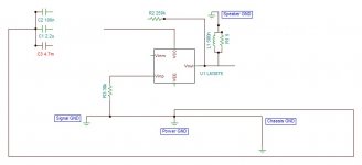
No worries, disagreements can lead to progress. The LM3875 has pretty good PSRR in the lower band and mounting a precision op-amp over it, we should be able to extend that capability throughout the whole audio band. Tom has already shown this works. The 5nH was a typo that should have read .5uH. The Thiele inductor value will rise the further we move from the output. Updated schematic. I have one question about decoupling caps, The LM3875 chip will have between 4 and 8MHz of bandwidth, the resonant frequency of 100nF should exceed this comfortably in theory but which kind of cap will do this the best in practice?
Attachments
Last edited:
...LM4780 is actually using two seperate LM3886 die.
LM4780 Audio Power Amplifier - Glenn's Design Log
Other than minor savings of PCB real estate, zero benefits from using it.
I used 2x LM3886TF as mentioned earlier, but I think I could save some area (maybe 20..25%) on the board below by going with an LM4780 (and smaller or vertically mounted resistors for the Howland network):
An externally hosted image should be here but it was not working when we last tested it.
There's a lot of relatively sparse routing and empty areas on the board, simply because it's rectangular with dimensions that are largely forced by having 2x LM3886TF that need to be spaced some distance apart. The trace density at certain areas on the right is fairly low, but there aren't too many options to save board area for this form factor with 2x LM3886.
(Yet another alternative for lower power is the TDA7265B, but that will have to use a different nesting topology derived from the MiniRef).
The 5nH was a typo that should have read .5uH. The Thiele inductor value will rise the further we move from the output. Updated schematic.
You just shorted your output to GND through the inductor.
I have one question about decoupling caps, The LM3875 chip will have between 4 and 8MHz of bandwidth, the resonant frequency of 100nF should exceed this comfortably in theory but which kind of cap will do this the best in practice?
I suggest reading the Supply Decoupling section of my Taming the LM3886 website.
~Tom
- Status
- Not open for further replies.
- Home
- Amplifiers
- Chip Amps
- An LM3875 composite amp