Lots of us have built gainclones and most of us have outgrown them. It's time to look toward the future and repurpose those chips into something more SOTA. We have some examples of how successful composite amps can be from the esteemed Mauro Penasa with his Howland pump inspired MyRef and from Tom Christianson's own unique implementation of the LM3886. I'm ready with some teflon sheets, copper foil and glue to start prototyping some designs and I'm hoping to get a crash course with LTSpice along the way. The design goals are for a small, pristine clean amp that can use just about any power supply. Here are the projected specs:
30W/8R 50W/4R per channel with THD+N of 0.0002% from 20Hz-20KHz with full bandwidth of 5Hz-50KHz +/-3dB
30W/8R 50W/4R per channel with THD+N of 0.0002% from 20Hz-20KHz with full bandwidth of 5Hz-50KHz +/-3dB
Last edited:
You may want to check out my MiniRef 1875:
http://www.diyaudio.com/forums/chip-amps/184165-miniref-schematic-pcb-layout.html
It's now at PCB version 1.04, with upgrades to the topology and implementation over the last 2 years, and the audible sonics are comparable with the best nested topologies, even with modest chipamps like the TDA2050. The key features are excellent sonics with inexpensive and commodity parts, providing modest output power in the 15 to 20W range into 8 ohm bookshelf-sized speakers.
For higher powers in the 80W per channel range, I also have a prototype dual parallel LM3886 design called the MyRef X2. It is fully functional and stable, but some further work may be needed to bring the sonics on par with the MiniRef v1.04.
BTW, the layout is critical with most nested topologies - point-to-point or breadboard/perfboard-type layouts may have too many parasitic elements to allow easy optimization for sonics. You may have to lay out a PCB with carefully chosen ground planes to be able to get to the level of the existing designs, some of which have taken years to optimize.
Edit: AFAIK, there isn't an LM3875 composite design in the DIY domain, but that may simply be due to the easy availability of the LM3886, which has comparable specs. If I were to develop a fresh design for 4-ohm loads, I'd probably go with the LM4780, dual parallel monoblock.
Last edited:
Yeah, youtube has some tutorials but they're not likely to be as helpful as direct input from experienced SPICE users. Hey linuxguru, that's a cute current pump implementation. Do you have any experience with Oscad?
... Do you have any experience with Oscad?
I've used OrCAD on DOS about 25 years ago, but now all my layouts are done with Eagle.
I'm glad to see I've inspired some thinking on the topic of composite amplifiers. That's definitely the way to go if you want performance.
The MyRef-series is a Howland current pump. If you are interested in the design challenges, including stability challenges, of this type of circuit, I encourage you to read Bob Pease's article on the subject (National Semiconductor (now TI) AN-1515). It's actually a very accessible read for anyone with some electronic design skills.
Note that to get the power specs you list, you need to do an excellent job with the thermal management on the LM3875. In particular with 4 Ω load, the thermal management gets to be a real challenge.
Also keep in mind that the THD at higher frequencies (1 kHz and above) is largely determined by the PCB layout. You need to minimize the inductance of the layout, in particular the inductance in the ground reference for your error correction opamp.
You can find a ton of pointers on my Taming the LM3886 website. I use the LM3886 as an example, but the same math applies to any other chip amplifier.
Should you be curious about the performance of your circuit once you have it built, I'll be happy to measure it for you. I should have an APx525 before the end of the year and intend to offer my test&measurement services to the DIY Audio crowd.
And should you want to take a shortcut and get to a working circuit faster, you can always check out my Modulus-86. Should you prefer the LM3876 rather than the LM3886, you can use the LM3876 in a Modulus-86 board as well. As far as I can tell, the LM3876 is the same IC as the LM3875 except the former offers a mute function and is pinout compatible with the LM3886.
~Tom
.
<< I'm hoping to get a crash course with LTSpice >>
YouTube is the place.
.
LTSpice. If your a beginner then click the link in my signature.
... As far as I can tell, the LM3876 is the same IC as the LM3875 except the former offers a mute function and is pinout compatible with the LM3886.
I can confirm that the LM3876 is not just an LM3886 with smaller output transistors. It behaves differently, and will not work in a stock MyRef (output sticks to -Vs on power up). This suggests that the small-signal internals of the LM3876 differ from the LM3886. It could well be a modified LM3875 as you conjecture.
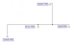
I am going to put this amp together in an unorthodox manner and start with the grounding topology. Tom is right to point out the final distortion numbers are likely to depend on how cleverly we can tie this amp together. While you guys look over the grounding scheme, you should start imagining the components working within it.
Attachments
I can confirm that the LM3876 is not just an LM3886 with smaller output transistors. It behaves differently, and will not work in a stock MyRef (output sticks to -Vs on power up). This suggests that the small-signal internals of the LM3876 differ from the LM3886. It could well be a modified LM3875 as you conjecture.
Perhaps we should start a separate Debugging the LM3876-MyRef thread.
Anyway... The LM3886, LM3875, and LM3876 are not that different on the spec sheet so I'm a bit surprised you're having trouble. The equivalent circuit schematics for the LM3886 and LM3876 are identical. Looking at the spec tables, it seems the input stage is identical between the two as they both have the same input bias current. My guess is that the main difference between the LM3876 and LM3886 is the biasing of the output stage and the number of output devices used. I base this on the quiescent current and the drop-out voltage specs. The protection circuits would be quite different as well - or at least set for the lower current limits on the LM3876.
The LM3875 is different (slight tweaks to the biasing of the VAS and input stage, nothing earth shattering). Aside from these small tweaks, it appears to be the same IC as the LM3876.
The open-loop gain for the three ICs is the same (or very close). They all have 115-120 dB AVOL and 8 MHz bandwidth (2 MHz worst case). I would be surprised if a circuit designed for one of the ICs wouldn't work with any of the other (obviously, observing the pinout difference on the LM3875). I wonder if you're seeing a start-up issue where the protection circuit of the LM3876 engages and clamps the output voltage on start-up. The higher current limit of the LM3886 could allow the circuit to start up by, essentially, brute-forcing through the start-up issue. You may be able to simulate this. Another approach would be to look at the supply current during start-up with a storage scope.
~Tom
I am going to put this amp together in an unorthodox manner and start with the grounding topology. Tom is right to point out the final distortion numbers are likely to depend on how cleverly we can tie this amp together. While you guys look over the grounding scheme, you should start imagining the components working within it.
I suggest simulating the ground scheme. Include the supply capacitance (including parasitics) along with the impedance of the ground traces (at least the resistive and inductive parts). You can get pretty good estimates for those numbers from the on-line PCB trace and plane inductance and resistance calculators. I'll see if I can dig out a link to one.
~Tom
Yes Tom, that was my next step after optimizing a Thiel network for the output. May I ask where you got the model for the LM3886? I will eventually need the LM3875 model and depending on the chip we decide to use for precision, I'll need those models too. By the way, I downloaded the TINA-TI package and it is is a treat. I have it running on an old celeron and it runs fine but strangely, I couldn't find any of the Analog Device chips in that package either. I'm currently playing with three spice modeling packages and can't make up my mind which to use. For the record, I'm looking at a 22V swing to get 30W/8R. How close to the rails should I expect to get when the amp is loaded? I'd like to completely avoid clipping this amp and none of my sources output more than 2V and they are all single ended so where would you set your input sensitivity (impedence)?
There are at least three different designs of composite amps here. inverted, non-inverted, current pumps and different combinations of feedback loops. Do you want to use a servo for DC output correction? will all the opamps have the same voltage requirements and need voltage regulators?
You are going to need to make some choices!
You are going to need to make some choices!
Perhaps we should start a separate Debugging the LM3876-MyRef thread.
...
The higher current limit of the LM3886 could allow the circuit to start up by, essentially, brute-forcing through the start-up issue. You may be able to simulate this. Another approach would be to look at the supply current during start-up with a storage scope.
It could well be related to protection and/or startup - IIRC, the SPiKe protection of each of these chipamps differs, and it is not shown on the equivalent circuit in the datasheets.
Part of the problem is that there is no published transistor-level simulation model of any of these chipamps, leave alone comprehensive models with SPiKe protection included. The few models that are out there are behavioural and/or encrypted and/or just plain borked.
In simulation, I substitute an approximate LM1875 model for any chipamp, and conservatively increase Cdom in the real prototype to about 2x what the simulation requires for stability. It works well for the LM1875, and kinda works for the LM3886.
That information is likely to be in the datasheet...............For the record, I'm looking at a 22V swing to get 30W/8R. How close to the rails should I expect to get when the amp is loaded? I'd like to completely avoid clipping this amp and none of my sources output more than 2V and they are all single ended so where would you set your input sensitivity (impedence)?
It is for the 3886.
22V swing is 22Vpk output.
You need loaded supply rails about 3V (check datasheet to confirm) above that to avoid clipping at 30W into 8r0, i.e. +-25Vdc when fully loaded.
Expect the quiescent rails to sag by 2V to 5V when fully loaded, so start with ~ +-28Vdc for your 30W target. That is roughly what you will get from a 20-0-20Vac transformer.
For 22Vpk from a 2Vac Source you need a gain of 22/sqrt(2) /2 = 7.8times (+17.8dB).
What is the minimum gain of the chip for just barely adequate stability margins?
A bit more gain than the minimum improves the stability margins. The 3886 likes to work around the 27times gain for good margins into a normal 2way 8ohms speaker.
You will certainly have to attenuate a 2Vac Source to avoid clipping and that is under the control of the OPERATOR !!!!
You have a lot of decisions to make. or build a kit exactly as described by the designer.
Last edited:
How do you access Cdom (Miller cap/VAS feedback)?I..............and conservatively increase Cdom in the real prototype to about 2x what the simulation requires for stability. It works well for the LM1875, and kinda works for the LM3886.
How do you access Cdom (Miller cap/VAS feedback)?
This is actually an external feedback cap (outside the chipamp as well as opamp) that sets the gain rolloff for the combined (composite) MiniRef amp. I think it has the designations C10/C20 on the v1.02 schematic. Values typically range from 22pF to 100pF (faster the outer opamp, the larger this capacitor to retain overall loop stability).
May I ask where you got the model for the LM3886?
From TI's website: LM3886 Tools & Software.
I will eventually need the LM3875 model
That's available on TI's website as well: LM3875 Tools & Software.
I downloaded the TINA-TI package and it is is a treat. I have it running on an old celeron and it runs fine but strangely, I couldn't find any of the Analog Device chips in that package either.
TINA-TI is not bad. The schematic editor could be better, but the simulation engine is pretty solid.
Of course you won't find competitor's parts in a TI simulator. You won't find TI or ADI parts in LTspice either. If ADI publishes their models in PSpice or regular spice format, you can probably add them to LTspice or TINA-TI with a minimal amount of fuss.
I'm currently playing with three spice modeling packages and can't make up my mind which to use.
They all have their advantages and drawbacks. I use TINA-TI and LTspice interchangeably. If I use LT parts, I use LTspice. If I use TI parts, I use TINA-TI. The schematic editor is better in LTspice, but the waveform viewer in TINA-TI really rocks. None of them are as powerful as the Waveform Graph XL in Cadence, but none of them are as expensive either. 🙂
For the record, I'm looking at a 22V swing to get 30W/8R. How close to the rails should I expect to get when the amp is loaded?
As AndrewT has pointed out, you can find this information in the spec table of the data sheet. If the number is listed in the "limit" or min/max column, it's tested in production. Typical numbers are found by characterization of a large sample size of product. The parameter you're looking for is Vod (Output Dropout Voltage).
I'd like to completely avoid clipping this amp and none of my sources output more than 2V and they are all single ended so where would you set your input sensitivity (impedence)?
2 V RMS = 2.82 V peak. Sensitivity = Voutpeak/2.82. Done.
I'm a bit concerned that these types of questions show up... Perhaps you should take a deep breath, slow down a bit, and read some data sheets. Perhaps even crack open a book or two... I link to a couple of good ones in the Resources section of my Modulus-86 website.
There are at least three different designs of composite amps here. inverted, non-inverted, current pumps and different combinations of feedback loops.
For a comprehensive study of the Howland current pump, I suggest reading Bob Pease's article on the subject. That's National Semiconductor Application Note AN-1515. You'll find a link to it in my post earlier in this thread (post 4-5 or so).
Inverted vs non-inverted. If you operate the LM3886 in non-inverting configuration, you'll get ever so slightly higher THD, however, in a composite amp this difference will be reduced way below the noise floor. I'd say go with the solution that provides the lowest complexity and best stability. You can figure this out by simulation.
You are going to need to make some choices!
Isn't that what design engineering is about? 🙂
Part of the problem is that there is no published transistor-level simulation model of any of these chipamps, leave alone comprehensive models with SPiKe protection included. The few models that are out there are behavioural and/or encrypted and/or just plain borked.
Of course the models are encrypted. The manufacturers don't like to give away their designs either... I actually find the TINA-TI LM3886 model linked to above to be pretty good. It's a tad optimistic on the bandwidth but is good enough to get close to the optimum point for stability. My only gripe is that it doesn't include the coupling from the supply pins, i.e. the model has infinite PSRR.
~Tom
Last edited:
I appreciate the concern and the textbook reply but I was looking for a real world response of something less obvious. I should have asked how much dynamic headroom I should allow (ie: 16dB, 20dB or higher) to avoid clipping on strong transients. Some have told me this is totally dependent on the loudspeaker being used but given the symbiotic relationship, I was looking for a more practical guideline from someone more familiar with the Overture chip line.tomchr said:2 V RMS = 2.82 V peak. Sensitivity = Voutpeak/2.82. Done
An unloaded, fully rectified 28V seems high to end up with 22V. This is Class AB and the quiescent current is pretty low. I was hoping to use a stock of 18VAC transformers I found. I should be able to address any sag tuning capacitance with 25.2VDC.
Last edited:
- Status
- Not open for further replies.
- Home
- Amplifiers
- Chip Amps
- An LM3875 composite amp