Ah THAT one 🙂
Reminds me for some reason of the "wrong hotel circuit" or "French hotel circuit" as we call it. It is the lower circuit that is not so safe for a few reasons. It is therefor VERBOTEN here (zintolo will like the teutonic capitals).
Reminds me for some reason of the "wrong hotel circuit" or "French hotel circuit" as we call it. It is the lower circuit that is not so safe for a few reasons. It is therefor VERBOTEN here (zintolo will like the teutonic capitals).
Attachments

Last edited:
Roberto, perhaps it is better to start with assessing more closely what you have been looking at that has started your interest. What 'old e-cap' impedance data were you looking at? I'm not sure I have come across specific impedance curves of specific commercial e-caps (as compared to generalised curves) before about 1970-80. And I guess there is a concern about doing modern day impedance measurements on vintage caps as the results may need some interpretation for aging, use, and pre-conditioning.
And an awareness is also needed as to what frequency range is of importance - as you may have been comparing new radial e-caps meant for pcb use in smps that have a flat low impedance extended out to the MHz region, compared to axial caps that aren't designed for ESR type impedance to extend out so far (especially when used on a tag board with long lead and circuit loop length).
You may find that just using long lead lengths for modern radial caps, and a low value resistor in series, achieves the effective impedance you think you are after.
As diy members its important to remember that we do indeed try things, experiment, and boldly go where in some cases we shouldn't venture. Diyers like to say "What if I do this" and in my mind its important to try things instead of being negative. Its been suggested at least I pick up the vibe that tube audio in some members minds is less than adequate. I for example graced my listening room for years with different pieces of equipment and if truth be told I could have purchased a new Corvette with the money I have spent over the years.
Audio in my mind satisfy's an individuals need and or perception of what sounds good to them or trips their trigger. To some its SS gear and others its tube gear and each of us needs to respect each others opinions in this regard...again my opinion.
Probably the best course of action instead of putting forth a negative reply is simply state as an answer what the results would be IF one was to add for example an inductor to a capacitor. One might also try different capacitors in order to come up with the sound they are looking for and are satisfied with... again just an opinion here.
Jean-paul - you are inserting pre-conditions in your responses that the OP has not imposed. The OP has said nothing about 'HiFi' as an objective, or trying to 'reproduce signals the way they are'. If you can't limit responses to what the OP has an interest in, then best not introduce your own personal red-herring responses. Stick with the OP's intent for this thread.
OK. Please try to explain what happens when one deliberately adds coils to good caps. I thought reproducing signals they way the source offers them was/is one of the main goals also with vintage stuff? That a PSU converts mains AC to DC filtering the ripple so a nice flat non sagging DC voltage is being fed to the circuits?
I like to point out that I gave a solution that may very well suit the OPs wishes without making the part perform like something else than being mainly a capacitor. But, besides a direct racial slur, no real reaction.
@zintolo: for desired degraded performance I suggest to have large can caps in series to up the ESR, making it possible to lower the value to the equal value of the old caps (modern caps have often higher capacity value in a smaller casing) and such of course with voltage balancing parallel resistor over each cap as good design practice. It would be advisable to have highest possible voltage ratings as these will be lower µF value. One could measure the ripple voltage and try to make the new PSU having as much ripple voltage as the old PSU.
Pointless discussion really, I will go create something. Bye!
Last edited:
BEST path to Audio Nirvana is to buy stuff from sleazy pawnshops and use as-is.
No silly recapping, pot/switch/connector cleaning, no grounding chassis to non existing mains plug ground pin, I would be hesitant to vacuum accumulated dust out, for fear of removing fairy dust with it.
Guaranteed TONS of Vintage Mojo performance.
No silly recapping, pot/switch/connector cleaning, no grounding chassis to non existing mains plug ground pin, I would be hesitant to vacuum accumulated dust out, for fear of removing fairy dust with it.
Guaranteed TONS of Vintage Mojo performance.
Roberto, perhaps it is better to start with assessing more closely what you have been looking at that has started your interest. What 'old e-cap' impedance data were you looking at?
Thanks trobbins,
everything started by measuring an old e-cap that was installed on the power supply of a friend's IA with an LCR bridge meter, and comparing it with new caps I had on hand. New ones showed an higher difference between the 100 Hz and 10 kHz, whilst older ones around 25-35% difference. The sound was different using the older vs newer caps (guitarists and bassists would define it "feel under the fingers"). The idea started from there, to see how the sound would change by changing the characterystics of the supply caps. Then I saw an application on an old radio of the 30's that is in my family house and recently blew up (a cap shorted and the PT blew) after almost 90 years. The few times we switched it on in the last decades (there's an old variac before the radio, originally foreseen due to the variation in voltages with old lines, now used because we switched to 230V), we talked about the early decades of the previous century, when instead of frequencies, radios show cities and that was the standard way to call the stations. And that radio makes even new transmissions (the few in that range, nowadays) sound like we were in that period while listening to those stories. OT: part of my family's house has been switched to museum to show children how life was between last decades of 19th century and first decades of 20th century, and that radio is in one of the rooms and sometimes switched on to show them what was the state of the art of the technology those days.
I'm not looking at sonic nirvana, nor thinking a simple inductor will make the world better. I'm just asking if and how I can apply an inductor and/or a resistor in series to make a capacitor (so the power supply, so the sound) behave differently and obtain different results. Not better, nor worst. Different. Then if someone else has done something similar before and can give me guidelines.
EG: 0.47 Ohm is ok when the cap is above 220u, otherwise go around 0.22 Ohm; 50 uH are too much in general, better to go around 10 uH up to 100 uF and 33 uH above that.
That's it.
Thanks again.
Roberto, are you focussing on e-caps used in valve equipment (given the historical aspect), or just solid-state equipment, given your interest was piqued by what appears to be an early solid state IA.
Do you have the measurement plot of the old e-cap, and know what brand and model it was? Were you going to use that equipment for testing?
Most commercial equipment is designed such that if the e-caps are 'ok', then there will be no noticeable (to the ear) difference, unless either the e-cap has significantly degraded, or the audio equipment is poorly designed. You may be able to discern some difference from certain measurements, such as noise versus frequency, or different distortion types versus frequency, but in general well designed equipment won't or shouldn't show up differences in power supply component parts.
@zintolo It would be nice if you could uploads some fotos of your personal museum. Fiddling with these series R or L is useless imho and will give no audible difference imho.
Modern quality electrolytic capacitors have lower ESR hence poorer frequency response and higher distortion. An external resistor does not provide a cure for the problem.
Also the IA was a tube amp, a Marshall guitar tube amp.Roberto, are you focussing on e-caps used in valve equipment (given the historical aspect), or just solid-state equipment, given your interest was piqued by what appears to be an early solid state IA.
I don't have the data with me now, but I will report it here. It was an old LCR blue cap. I don't have a full plot, just the values at 100 Hz and 10 kHz read with a DER EE DE-5000.Do you have the measurement plot of the old e-cap, and know what brand and model it was? Were you going to use that equipment for testing?
Thanks, it is just few euros to try it, even if I'll hear/measure no differences I will report the results.in general well designed equipment won't or shouldn't show up differences in power supply component parts.
Ok so we are talking about guitar amps in general - which is a notably niche and different type of amplifier group than general audio amplifiers.
It will be interesting to see the data.
Do you recall the amp, and date of manufacture (assuming it was after 1962 when LCR started), or have a link to the circuit?
Did you only test one sample from the amp (perhaps there was only one main filter e-cap, and the other caps were smaller value e-caps)?
Did you test the same (or equivalent) model e-cap from the same manufacturer, given that LCR don't appear to make e-caps nowadays, or are you just aiming to make a modern cap perform like what a vintage cap may have represented? One issue you need to appreciate is that capacitors age, and that can change parameters like ESR (and that may be chemistry and frequency dependant), so a measurement made on a vintage cap that has been used is not likely to align with the same measurement if it were made when the cap was made (first used).
Last edited:
I understand that in Hi-Fi- it is better to have all parameters as stable as possible to keep curves under control, so THD. For the old radio it is not that important, and even less for the guitar amp that is designed to drop the supply under heavy load.Ok so we are talking about guitar amps in general
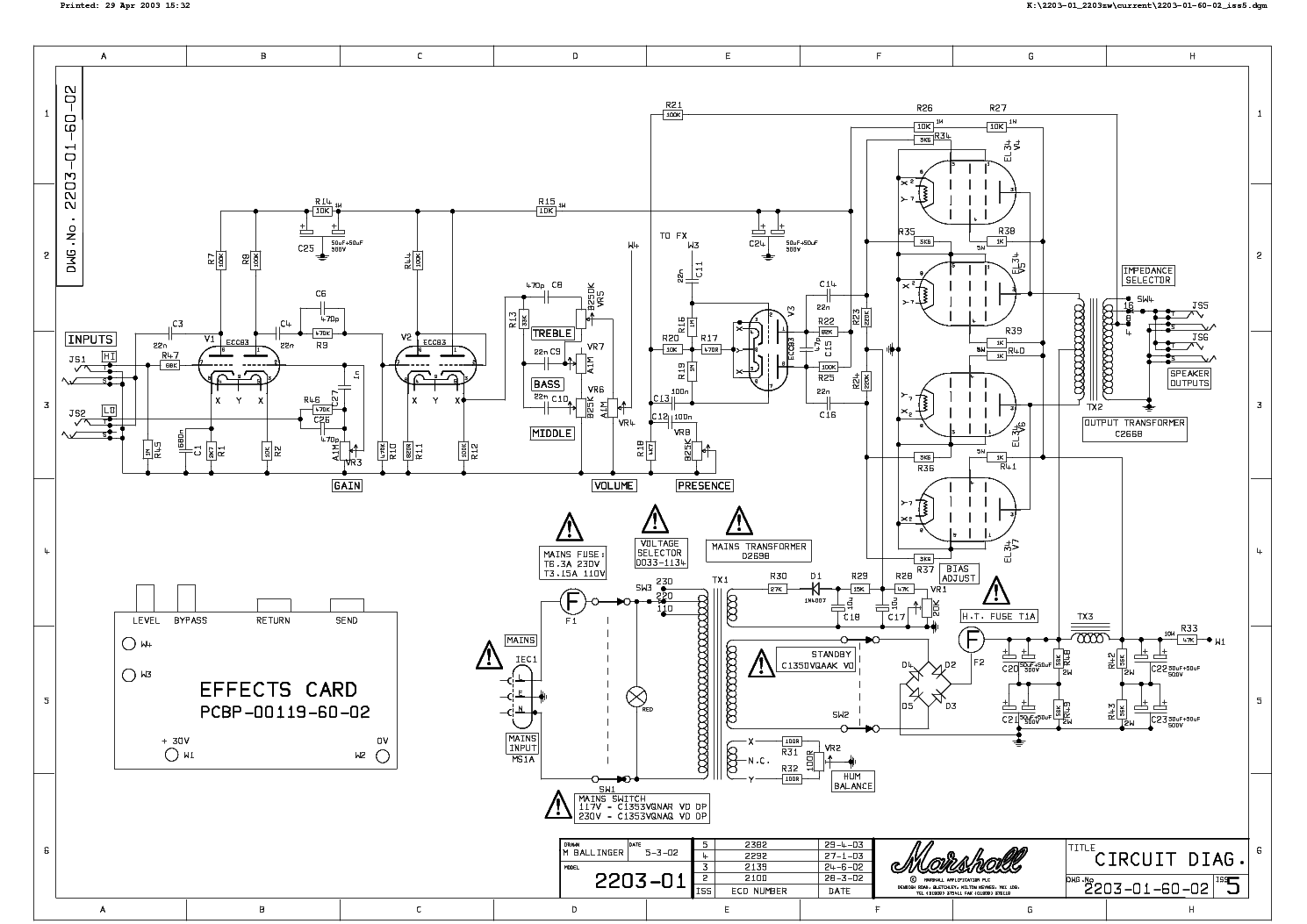
It's a Marshall 2203, but the link to the circuit is not working at the moment (DrTube site is down today). OT Raa is 3.4 kOhm, so a very steep loadline.Do you recall the amp, and date of manufacture (assuming it was after 1962 when LCR started), or have a link to the circuit?
All caps are 50+50uF and all tested similar.Did you only test one sample from the amp (perhaps there was only one main filter e-cap, and the other caps were smaller value e-caps)?
I'm curious on the possible audible effects (if any) of a modified cap (adding in series a resistor or an inductor).Did you test the same (or equivalent) model e-cap from the same manufacturer, given that LCR don't appear to make e-caps nowadays, or are you just aiming to make a modern cap perform like what a vintage cap may have represented?
So film caps should be the best candidates to make them worst, being the most stable, am I right?One issue you need to appreciate is that capacitors age, and that can change parameters like ESR (and that may be chemistry and frequency dependant), so a measurement made on a vintage cap that has been used is not likely to align with the same measurement if it were made when the cap was made (first used).
As its a solid state HT rectifier I would not expect the HT to sag that much so its not a change in gain as the note is sounded. So I think modern caps would work better, and bigger will give less 100Hz intermodulation.
- Home
- Amplifiers
- Tubes / Valves
- An inductor to make new e-capacitors seem more vintage?