Yup, the "scare quotes" are real.
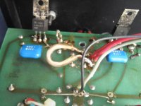
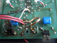
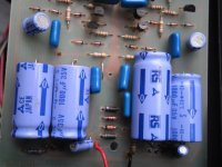
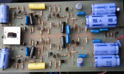
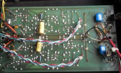
A friend has asked me to repair his preamp, it looks like a PS IVa VK on the outside. Inside....it looks like some things have been changed. Note that the circuit board has been truncated and I'm guessing the sawed-off section contained the original power supply. The (leaking!) mess of a power supply can't possibly be original. For what it's worth, the crispy resistor is the current limiter for the panel LED. Ohm's Law says this should be a 2 W part instead of the half-watt one that was. That's not the best of the "improvements" here.


I tried searching for a "gut shot" of this model but came up with nothing. I'm especially curious what the original capacitors were. Anyone know? Numerous witness marks show that these electrolytics and orange drops weren't the original parts.

Here's a schematic I traced from the PCB, before I found the documentation for this preamp. I assigned reference designators by board layout so they don't match the diagram that's in the owner's manuals. Component values are as I found them, including the swapped caps. (C10 I had to measure, it's the little 150 pF polystyrene cap in the photo above.)

Thanks in advance for any enlightenment.
A friend has asked me to repair his preamp, it looks like a PS IVa VK on the outside. Inside....it looks like some things have been changed. Note that the circuit board has been truncated and I'm guessing the sawed-off section contained the original power supply. The (leaking!) mess of a power supply can't possibly be original. For what it's worth, the crispy resistor is the current limiter for the panel LED. Ohm's Law says this should be a 2 W part instead of the half-watt one that was. That's not the best of the "improvements" here.
I tried searching for a "gut shot" of this model but came up with nothing. I'm especially curious what the original capacitors were. Anyone know? Numerous witness marks show that these electrolytics and orange drops weren't the original parts.
Here's a schematic I traced from the PCB, before I found the documentation for this preamp. I assigned reference designators by board layout so they don't match the diagram that's in the owner's manuals. Component values are as I found them, including the swapped caps. (C10 I had to measure, it's the little 150 pF polystyrene cap in the photo above.)
Thanks in advance for any enlightenment.
Perhaps the original used a CRCRC type of PS filter and an ex owner wanted to have crappy regulators instead. Early 80s there was quite a crappy regulator craze. By the look of the caps, this unfortunate development probably happened somewhere in euroland.
What is your aim? To restore it to a factory state or extract a bit more in terms of sound?
What is your aim? To restore it to a factory state or extract a bit more in terms of sound?
Ok, i was wrong. The circuit indicates 3-terminal regulators were originally used. No idea what caused the upgrade.
I had this preamp, still have chassis.
I cascoded the differential pair on each stage, changed to better metal film resistors. Changed the electrolytics to bipolar, The board foil is fragile so I used solder wick. Yes a CRC power supply prefilter is good, also bypass the voltage seting resistors on the regulators with 10 to 100uf to rediuce noise and ripple.
I cascoded the differential pair on each stage, changed to better metal film resistors. Changed the electrolytics to bipolar, The board foil is fragile so I used solder wick. Yes a CRC power supply prefilter is good, also bypass the voltage seting resistors on the regulators with 10 to 100uf to rediuce noise and ripple.
Last edited:
Perhaps the original used a CRCRC type of PS filter and an ex owner wanted to have crappy regulators instead. Early 80s there was quite a crappy regulator craze. By the look of the caps, this unfortunate development probably happened somewhere in euroland.
What is your aim? To restore it to a factory state or extract a bit more in terms of sound?
My initial aim is to figure out what the factory state was (with the electrolytics especially) and then go from there. Since the rework is so highly dubious I want a nominally sane starting point. Are the output couplers really supposed to be 330 uF? That sounds like a good way to check for platter rumble. 🙄
And for sure I'll be building a fresh power supply for it, using a proper circuit board with power/ground planes and everything. But right now I'm focused on getting the preamp board put right.
Pictures of my non-working PS IVa
Pictures of my non-working PS IVa - hopefully will help. Maybe also someone can help me fix this. The rails on the board were very fragile, some broken, and it looks like years ago that I crudely tried to fix and work around them..
Pictures of my non-working PS IVa - hopefully will help. Maybe also someone can help me fix this. The rails on the board were very fragile, some broken, and it looks like years ago that I crudely tried to fix and work around them..
Attachments
Are the output couplers really supposed to be 330 uF?
Into even a 10k load, a 10uF nonpolar output capacitor should be fine.
That will give a 2Hz rolloff.
Last edited:
On the later IV and IVH the regulated voltage is supposed to be between ±28V and ±32V.
The output cap was a 100uF with either a 0.1mylar or 0.01 polystyrene bypass.
If this helps, here's the IVH schematic from P.S. Audio (not from the manual):
![4h-2[1].jpg](https://www.diyaudio.com/community/data/attachments/641/641438-6dd771a9ea72ff82d1fa0e58dd5484a5.jpg?hash=bddxqepy_4 "4h-2[1].jpg")
The output cap was a 100uF with either a 0.1mylar or 0.01 polystyrene bypass.
If this helps, here's the IVH schematic from P.S. Audio (not from the manual):
Last edited:
![4h-1[1].jpg](https://www.diyaudio.com/community/data/attachments/641/641443-4bbd622643a8c3e994fc91db2f5c9110.jpg?hash=S71iJkOow- "4h-1[1].jpg")
the 2 stage design is good. however the gain of 52 in the output stage could be noisy and the connection point of the MM/MC gain switch ruins the PSRR and differential noise cancelling ratios.
a single transistor or tube can do the first stage and an op amp like an opa2134 can perform the second stage duties. I keep the final stage gain to 5 to keep the s/n > 80db.
a single transistor or tube can do the first stage and an op amp like an opa2134 can perform the second stage duties. I keep the final stage gain to 5 to keep the s/n > 80db.
Pictures of my non-working PS IVa - hopefully will help. Maybe also someone can help me fix this. The rails on the board were very fragile, some broken, and it looks like years ago that I crudely tried to fix and work around them..
Hi,
Here's my story of my last encounter with this phono.
Last year someone brought the same phono to me to see if it can be repaired. To my horror, its possibly one of the worst examples I've seen. The PSU box that came with was a DIY'ed one, and the pcb had an aged wrinkled lacquer on it. There were numerous tell tale evidence its been worked (hacked) in the past. Many pcb tracks had lifted, some broken, brittle and numerous hardwired connections on board. It was a horror story unfolding. There was a loud hum without signal on both channels. I wish there was an alternative new pcb where I could transfer most of the essential devices and upgrade other common parts but I know I didn't have any PC design skills to get one made, neither was there any to be found. There wasn't any schematic either and no enthused to trace the circuitry. A brand new well designed pcb was the total solution. I managed to fix it up and quickly return it to the owner. I had lost interest and enthusiasm in trying to help this phono any further. That was that.
Last edited:
I have posted my PS Audio IVa on eBay. Serial number 0003C with original power supply. In great condition. Rare PS Audio IVa MC/MM Phono Preamp with Original External Power Supply | eBay
- Status
- Not open for further replies.
- Home
- Source & Line
- Analogue Source
- An "improved" PS Audio PS IVa phono preamp