Your "Sound out" measures the DC offset. The target there is zero. You
shouldn't have trouble trimming it down to below say 20mV.
You can keep your R7/R8 meters on mV scale for now. I don't know what
their mV limits are, but usually they can do at least 200mV. There's no
need to switch to V scale until you've reached the limit.
You can follow Dirk's instructions. The main thing is to alternately adjust
P1 and P2 to increase the bias current while keeping the DC offset fairly low.
Keep doing that until the R7 and R8 voltage reach your target.
I would just add that some meters when set to MV will read "0" or a hash mark or something like that when you exceed the MV range. Be careful you are not doing that. Might switch them to V setting on r7/r8 just to be safe. And a note...when you are on the "V" setting you will be seeing decimals. Make sure your math is right and the decimal is in the right place...especially on the output.
You don't need the precision of the MV scale except for the DC offset which can exceed the MV scale pretty rapidly if you don't know what you are doing. No harm in it...but often times you will see like 400mv and then nothing and wonder what is going on.
You don't need the precision of the MV scale except for the DC offset which can exceed the MV scale pretty rapidly if you don't know what you are doing. No harm in it...but often times you will see like 400mv and then nothing and wonder what is going on.
I would go up to at least a few tens of mV before switching over to V scale.
Depending on the resolution/counts of his meters, he may just see zero when
he's currently at 1mV or so.
Depending on the resolution/counts of his meters, he may just see zero when
he's currently at 1mV or so.
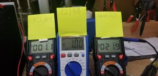
To sum up:
These are the targets I'm working toward:
But I want to get to:
R7 0.4V
R8 0.4V
Sound Out target ~20mV
These are the targets I'm working toward:
But I want to get to:
R7 0.4V
R8 0.4V
Sound Out target ~20mV
Correct.
Remember that 0.4V is 400mV, if your meter doesn't autoscale, which it probably won't.
And let's use the proper terms, It's "Bias Voltage" or "Bias" across R7 and R8, and "DC Offset" measured on the speaker outputs.
Remember that 0.4V is 400mV, if your meter doesn't autoscale, which it probably won't.
And let's use the proper terms, It's "Bias Voltage" or "Bias" across R7 and R8, and "DC Offset" measured on the speaker outputs.
And then there was smoke.
I had gotten them up to 10 mV each.
Then they flipped to OL across all 3 multimeters. The smoke appeared to be coming from around P2.
I had gotten them up to 10 mV each.
Then they flipped to OL across all 3 multimeters. The smoke appeared to be coming from around P2.
Well, unfortunately something is likely wrong with the amp that caused it to do that. You are going to have to go back and check everything.
Something is wrong beyond any possible slight problem in adjustment.
What resistance values do you now measure across R5 and R6?
What resistance values do you now measure across R5 and R6?
Did you perhaps tried turning P1 and P2 back down? At those resistance values
your mosfets shouldn't be conducting current. Any possibility you had
a short at the output during the process?
You'll need to inspect and test for damages. It sounds like R8 is gone but
I wouldn't be surprised if Q3 is also damaged. The other source resistor
and mosfet should be tested. Also look for damaged around R3 and R4.
I recommend taking the board off and inspect both sides. Take clear,
in focus photo of both sides and post them and hopefully others can
help spot anything wrong.
Before that, can you check a few things?
- What resistance you see across the amp outputs?
- Measure the resistance across R5 and adjust P1 and see if you can
gradually go from zero up to about 1.5K and back to zero.
Then do the same with R6 and P2.
- Try probing around see if any parts (particularly the mosfets) are
shorted to the heatsink
Did you perhaps tried turning P1 and P2 back down? At those resistance values
your mosfets shouldn't be conducting current. Any possibility you had
a short at the output during the process?
Not sure, anything is possible. It all happened so fast.
Also look for damaged around R3 and R4.
R3 = 000.3 ohms
R4 = 8.0 ohms
- Measure the resistance across R5 and adjust P1 and see if you can
gradually go from zero up to about 1.5K and back to zero.
Then do the same with R6 and P2.
When I turned on the Multimeter for R5 the first reading was 82.4 ohms. I was able to get it down to .03 and then up to 1.1 and back to .03 ohms.
R6 started at 78.9. I was able to get it down to .03 and then up to 1.1 and back to .03 ohms.
What resistance you see across the amp outputs?
I get 26.8 ohms.
Try probing around see if any parts (particularly the mosfets) are
shorted to the heatsink
Not sure how to test the mosfets?
Posting this before I remove the board for further inspection.
Last edited:
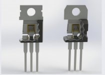
A mosfet's metal tab (the part that goes up against the heatsink) is connected to the drain of the mosfet. In our case, we don't want the drain to touch the chassis because the chassis is connected to other things. That's why we use an insulator like the silpads you are using.
The problem is it's very easy to damage the silpad with a metal burr or have some part of the mosfet metal pad touch the bolt and establish continuity between the mosfet drain and the chassis. This is when we see smoke.
So we test for continuity with a meter between the mosfet drain (middle pin) and the chassis. If there it reads 0 ohms or close to it, you've got a problem. So test for continuity between the middle pin of the mosfet and the chassis. On all the mosfets.
Attachments
Thanks. Understood. To test them I will remove them or is there a way to test before removing them from the board?
No, you have to test them while they are installed and in the amp. You are testing for continuity between the mosfet and the amp chassis. The heatsink. Basically, you want to see if the mosfet is touching the heatsink in any way. It should not be.
Right channel:
Q4 36.9 ohms
Q3 36.6 ohms
Left Channel
Q4 39.0
Q3 38.6
So all are blown.
I feel like I've not been careful enough when installing the mosfets with the pads. Appreciate any coaching before I install new ones.
I will remove the boards for inspection and photos.
Q4 36.9 ohms
Q3 36.6 ohms
Left Channel
Q4 39.0
Q3 38.6
So all are blown.
I feel like I've not been careful enough when installing the mosfets with the pads. Appreciate any coaching before I install new ones.
I will remove the boards for inspection and photos.
- Home
- Amplifiers
- Pass Labs
- An illustrated guide to building an F5