They aren't easily found here. I recently went through all of the threads on several forums looking for BOM/material lists and couldn't find any until some kind folks here started replying. The information that is out there is to build the generic PSU, and all the F5/F6 threads I've found either have pictures and *some* of the parts (but not all) or just pictures of what the person built making it difficult to try to determine the actual part used.
As a constructive remedy, I placed an order on Mouser and for the suggested parts I gathered and will create a sharable parts list with alternatives soon. I don't know how to get it posts in the build guides but perhaps the moderator can post somewhere for folks to find easily on the Pass or PSU build guide.
As a constructive remedy, I placed an order on Mouser and for the suggested parts I gathered and will create a sharable parts list with alternatives soon. I don't know how to get it posts in the build guides but perhaps the moderator can post somewhere for folks to find easily on the Pass or PSU build guide.
I have also ordered parts for the F5 boards and PSU and can easily convert those into Mouser projects if someone is interested. The F5 parts are pretty much identical to the forum store so I'm not sure if there is a conflict of interests or what not.
I can share if there is interest, but please note this is my first build so you'll have to do your own due diligence if using
I can share if there is interest, but please note this is my first build so you'll have to do your own due diligence if using
The issue isn't the parts for the F5; its for the PSU including the transformer make/model. I know that some find rifling through Mouser fun as do I for better/different types of parts but what I simply couldn't find is the BOM for Papa Pass's original schematic or the initial F5 build. The build guide is awesome, but it doesn't list the PSU parts. Its nice for nebies or newcomers to these builds to start from a single, well-known (and working!) reference point.
That is why Amp Camp and the resulting kits were so instrumental in my getting back into this, as well as using it as a vehicle to teach my son about how this stuff works and how wonderful the resulting builds can be! 🙂
That is why Amp Camp and the resulting kits were so instrumental in my getting back into this, as well as using it as a vehicle to teach my son about how this stuff works and how wonderful the resulting builds can be! 🙂
Yea.. I see your point. Ultimately I just printed out the schematic and filtered the parts with Mouser. There aren't actually that many choices for the filter caps that match the 10mm snap-in, up to 35mm dia... main ones are:
Nichicon LGU/LGY
United Chemi-con KMH/SMH
CDE 380LX/381LX/SPLX
An unrelated question... is the procedure of the 2x CL-60's in the guide linked from the product page sufficient for handling a 500VA transformer?
Nichicon LGU/LGY
United Chemi-con KMH/SMH
CDE 380LX/381LX/SPLX
An unrelated question... is the procedure of the 2x CL-60's in the guide linked from the product page sufficient for handling a 500VA transformer?
...
An unrelated question... is the procedure of the 2x CL-60's in the guide linked from the product page sufficient for handling a 500VA transformer?
Sufficient? In my experience, yes (although I'm on 240V).
Optimal? A bit more resistance might be better, especially if you're also bumping the capacitance to 22,000 or 33,000uF: SL22 16005 Ametherm | Mouser Ireland .
Cheers,
Jeff.
in my experience , being on 230Vac , one CL60 per 250-300VA Donut , having CRC of 33mF-0R1-33mF per rail , is resulting with perfect fuse value - T1A6 .....even if T2A5 wouldn't be too high
2) Depends on where you need the room. I'm starting to really like horizontal just because it makes the 300mm deep feel much bigger.
BTW, did you mean vertical here instead of horizontal?
I would expect so as the vertical mounting would free up space.... but maybe I'm misunderstanding this
I'm currenty building a F5 v2.0 and have a question about the 2SK170/2SJ74. I only have the 2SJ74 GR, is it better to use a 2SK170 GR also?
Sufficient? In my experience, yes (although I'm on 240V).
Optimal? A bit more resistance might be better, especially if you're also bumping the capacitance to 22,000 or 33,000uF: SL22 16005 Ametherm | Mouser Ireland .
Cheers,
Jeff.
Yes. All my FW amps have 500VA, except BA3, which has 1000VA....no problem has run for few years.
Russellc
Thanks, and all the four should be matched? Or matched per channel?yes
and hope that they're on top of Idss range
Last edited:
matched per channel
3mA Idss so pretty low, but matched. Hopefully it will work.
Another question, I have a big heatsink laying around that is 11,8 x 7,8 x 3,1 inch and 0,07 deg C/W. Should this be big enough to cool both channels?
Attachments

I have also ordered parts for the F5 boards and PSU and can easily convert those into Mouser projects if someone is interested. The F5 parts are pretty much identical to the forum store so I'm not sure if there is a conflict of interests or what not.
I can share if there is interest, but please note this is my first build so you'll have to do your own due diligence if using
I would personally be very interested in any Mouser projects for the the PSU. I purchased the F5 parts kit and so am good there. Thanks! LC
3mA Idss so pretty low, but matched. Hopefully it will work.
Another question, I have a big heatsink laying around that is 11,8 x 7,8 x 3,1 inch and 0,07 deg C/W. Should this be big enough to cool both channels?
if you have enough JFets , double them , using 2+2 per channel
you can even use slightly mismatched ones , as long sum of Idss of two up is close to sum of two down
that heatsink is certainly good for one channel ........... for 2 channels most probably nice lazy vent is only way
if you have enough JFets , double them , using 2+2 per channel
you can even use slightly mismatched ones , as long sum of Idss of two up is close to sum of two down
So parallel them? I have enough of them so I probably can get to 5-6ma per two.
Piezo power switch and epsilon 24
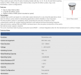
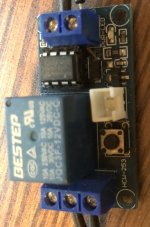
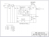
ok wasn't really sure where to ask this question but figured that someone here would be able to help me out. I am building the F-5 and liked the look of the Langir 12mm piezo switch to use as an on/off switch. Its a NO momentary contact type (specs attached). I also have the softstart board and I figured I would use a relay controlled by the Langir piezo switch to allow mains power to flow to the softstart board. For the relay circuit, I built out the AMB epsilon 24 power switch circuit (attached) which seems to work great until you put a piezo switch in the mix. Turns out AMB does not recommend piezos or capacitance type switches with the epsilon 24. I did purchase a different relay board on ebay and the piezo worked fine with that - i suspect because there was more voltage at the switch. But I really wanted to get the epsilon 24 to work with a piezo switch - so I thought - putting a capacitor in series with the piezo might allow the capacitor to build enough charge to overcome the resistance in the piezo switch itself and turn the board on. I used what I had laying around - a 22 micro farad electrolytic. And it worked but not reliably - so I figured add another capacitor in parallel - I got maybe a little improvement - but not so I could use it. On a whim I put that second capacitor in series with the first capacitor and got noticeable improvement. Then I added a third capacitor and the switch controls the circuit pretty much the way it should. see for yourself YouTube
My problem is that I do not know why this worked and I was hoping someone here with a lot more knowledge than me could help me understand what is going on. Also if you have any thoughts about how I could change out a component(s) on the board (maybe R2) to increase voltage at the switch - maybe I could get rid of the capacitors altogether? I know this is a big ask but I really am trying to learn as I go along.
Attachments
Hi all.
I've built my boards and PSU.
I'm waiting for the tx and Variac to arrive.
Any tips on tests I can carry out without power.
Thanks in advance.
I've built my boards and PSU.
I'm waiting for the tx and Variac to arrive.
Any tips on tests I can carry out without power.
Thanks in advance.
Hi all.
I've built my boards and PSU.
I'm waiting for the tx and Variac to arrive.
Any tips on tests I can carry out without power.
Thanks in advance.
Post closeup photos, verify parts orientation, check continuity with a meter to confirm the board matches the schematic.
- Home
- Amplifiers
- Pass Labs
- An illustrated guide to building an F5