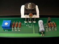
The first states number of turns : single.
That single means 1turn.
In practice this is usually ¾turn.
The second shows a sil or staggered pin arrangement. This fits in the post pic and is for a multi-turn trim pot, not a lay down flat version.
The third is a long version usually 10T or 15T and will not fit.
The pin layout is given for each of these types in their datasheets.
Sil type has 0.1" pin pitch. That is what the PCB is designed to fit.
Last edited:
I have already the Bourns 3286 staggered version with 1 turn (=3/4 turn?) fitted to the pcb. Not soldered yet.
Is there something wrong with using a single turn trimpot instead of a multiturn trimpot, as long as the pins fit the pcb?
Is there something wrong with using a single turn trimpot instead of a multiturn trimpot, as long as the pins fit the pcb?
.....................In the Bourns datasheets the pins are named "1", "2" and "3". When looking at examples of the cviller boards the pins were reversed! With a triangle shaped trimpot I have difficulties reversing it, because the pins are to short to bend that far.................
first post says they don't fit.I have already the Bourns 3286 staggered version with 1 turn (=3/4 turn?) fitted to the pcb. Not soldered yet.
Is there something wrong with using a single turn trimpot instead of a multiturn trimpot, as long as the pins fit the pcb?
second post asks if there is something wrong !
Yes, you have tried to fit the wrong type of trim pot !
I can fit the Bourns 3286 staggered version, but they will be reversed with pin 1 where pin 3 should be. My question was if this was fine as long as I turned them in the other direction.
The attached picture shows a factory F5 using something similar, but I can only make out XX86 in the number. Hopefully it is the Bourns 3286 that I have.
Why are single turn trimpots wrong, but multiturn trimpots right? I have checked how a usual trimpot works and it looks like it could work to reverse pin 1 and 3. Unless multiturn trimpots are much different.
Attachments
Last edited:
they aren't wrong
whatever you use - single turn or multiturn - you need to take one with proper pinout - single in line or "triangled"
whatever you use - single turn or multiturn - you need to take one with proper pinout - single in line or "triangled"
they aren't wrong
whatever you use - single turn or multiturn - you need to take one with proper pinout - single in line or "triangled"
Hypothetically, if I used a 3296 single in line, multi-turn (just to be safe) - would I be able to change it to counterclockwise if I felt like it, by fitting pin 1 where pin 3 should go and pin 3 in where pin 1 should go?
Would that be "improper"?
If not, and single-turn is fine, then I am good with my Bourns 3286 single turn, triangle pattern pinout.
I know it's an old post, but I do have a question about it.Ok, as promised. Here is the mains to the transformer primary -
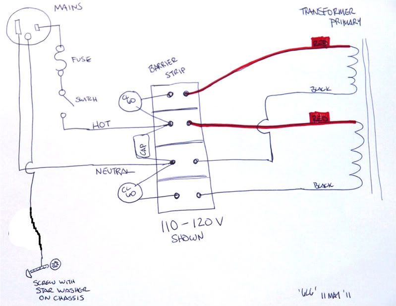
Can you explain the functions of the caps and thermistors? I've no idea what they do. Thanks!
James.
BUMP
In an F-5 amplifier board, can a SIL trimpot be reversed (pin 1 and pin 3 change places) with no problem other than me having to turn it counter-clockwise instead?
In an F-5 amplifier board, can a SIL trimpot be reversed (pin 1 and pin 3 change places) with no problem other than me having to turn it counter-clockwise instead?
I know it's an old post, but I do have a question about it.
Can you explain the functions of the caps and thermistors? I've no idea what they do. Thanks!
One thing worth note - that diagram shows a dual 120V primary wired for 120V - not 240V...
BUMP
In an F-5 amplifier board, can a SIL trimpot be reversed (pin 1 and pin 3 change places) with no problem other than me having to turn it counter-clockwise instead?
no prob
Is there something wrong with using a single turn trimpot instead of a multiturn trimpot, as long as the pins fit the pcb?
I wouldn't use a single turn trimpot because it won't give you a fine enough adjustment when you bias.
Those trimpots will vary with heat and a single turn trimpot will vary way too much with even an degree or so of twist. You will be in danger of blowing up your amp with just a flick of your finger.
it depends ......... of ratio of one's mileage/hysteria

FW amps are equipped with single turn trimpots .......
FW amps are equipped with single turn trimpots .......
Exactly why I got them, ZM. But good point, Dazed2, I will not dial the trimpot while sneezing.
I have come further with my build. Now I am mounting the Cviller F-5 (non-turbo) amp boards, but I have to mount them 1 cm above the mosfets. The mosfets and boards are mounted horizontal on a platform/L-bar. Too close I suspect!
Will this heat up the amp board and subsequently the Dale resistors and trimpots and cause them to change value?
I am thinking about using wires to the mosfets and mount the amp board well away from any heat source, on 4cm standoffs. Looks cool as well.
One thing that every guide neglects is clear illustrations of the connections to the switch, fuse and PEM. This is my first endevour into the perilous water of household mains. And I needz it.
Was there ever any consensus about stargrounding the PSU boards individually or tied together? I understood it like one should not make them the center of the star ground because you don't want all that noise in there.
Last edited:

I am thinking about using wires to the mosfets and mount the amp board well away from any heat source, on 4cm standoffs. Looks cool as well.
When using wire to extend connections to output devices, I always move my Gate stopper resistors off the PC board and directly connect them in-line with the Gate terminal of the Mosfet. This helps make the circuit more stable.
Hi all,
I set to build my F5, I think after reading throughout the thread I didn't find answers for the following questions:
1. Is a speaker protection module needed (given the output mosfets could fail and the speakers are costly)? I am asking as I bought the PCB from the store and must decide whether to use it or not. Does a speaker protection board affect the sound?
2. I'm using a 400VA transformer. Is a soft-start module needed? If used and as I bought the pcb from the store is there a building guide for it in the forum?
3. I bought on ebay matched Toshiba 2SK170/2SJ74 J-fets (quad) which are of the GR-type. What's the difference between them and the BL-type? Can I use them with the same results as the BLs?
4. I heard some diyers do not use the thermistors in the output section as they claim it affects the sound (!!)? Does it pose any risk in the mosfet operation or any change in the resistance values?
Could you please some experienced builder help me. Thank you - Christos
Hi all,
I set to build my F5, I think after reading throughout the thread I didn't find answers for the following questions:
1. Is a speaker protection module needed (given the output mosfets could fail and the speakers are costly)? I am asking as I bought the PCB from the store and must decide whether to use it or not. Does a speaker protection board affect the sound?
2. I'm using a 400VA transformer. Is a soft-start module needed? If used and as I bought the pcb from the store is there a building guide for it in the forum?
3. I bought on ebay matched Toshiba 2SK170/2SJ74 J-fets (quad) which are of the GR-type. What's the difference between them and the BL-type? Can I use them with the same results as the BLs?
4. I heard some diyers do not use the thermistors in the output section as they claim it affects the sound (!!)? Does it pose any risk in the mosfet operation or any change in the resistance values?
Could you please some experienced builder help me. Thank you - Christos
1. not necessary , but always welcome (I can mourn a little few things in amp , but I I'll be hysteric if anything happens to my spks , considering their rarity and slim chance of ever getting them in shape , in case of poof).
if you're golden ear-ed , maaaaaybe you'll hear bad influence of relay contacts ....
2. use CL60 ( as all FW and PL products are using) , or make soft start with few CL60 in series , in place of fixed resistors
3. current range - read datasheet ; you need to increase drain resistors for at least 1K ..... and to accept slightly lesser sound quality ...... but all that only if they are genuine
4.put them in , as they're intended ; for tossing them out , one needs mileage and it's still debatable is it really better without them in circuit
3. current range - read datasheet ; you need to increase drain resistors for at least 1K ..... and to accept slightly lesser sound quality ...... but all that only if they are genuine
Hi Zen Mod
you mean resistors R5 and R6 (refering to F5 v3.0 schematic)? Isn't this equivalent adjusting the trimpot so that R5/Rtrimpot compound rises per 1K? I noticed the difference between GR and BL is Idss range (2,0 - 6,5 vs 6 -12 mA - how does this relate to sound quality? (I hope the vendor was sincere and sold me toshiba originals).
Thanks - Christos
think ..... 😉
pot in parallel to , say, 2k2 is different to same pot in parallel to 3k3
with higher value of drain resistors there is slight increase of OLG , thus increase of total amount of feedback
though , do not worry - it'll be good amp
pot in parallel to , say, 2k2 is different to same pot in parallel to 3k3
with higher value of drain resistors there is slight increase of OLG , thus increase of total amount of feedback
though , do not worry - it'll be good amp
- Home
- Amplifiers
- Pass Labs
- An illustrated guide to building an F5