The big ones would work well in a single-rail Pass design (F3, etc.), but their voltage spec (63V) is overkill for a dual rail design.
Both of them are quality caps.
Both of them are quality caps.
I’m curious if they are any good. I can basically get a quad for free to test, but the store owner told me they were 15-20 years old…
Any concern for them being dried out or bad?
Any concern for them being dried out or bad?
They were certainly good caps when they were new. Unfortunately, I know absolutely nothing about the shelf life of electrolytics....
Hi folks another speaker related question. Apologies in advance, there may be a couple more of these as I try to determine my next monitors.
Wondering if anyone has driven any of the Revel Performa F series with an F5 or similar? Good fit, bad fit?
Wondering if anyone has driven any of the Revel Performa F series with an F5 or similar? Good fit, bad fit?
Within what time frame would the recipient have to complete a project before he surrenders the chassis?Make sure whoever get the chassis actually builds something in it….
I mean for some of us that's measured in months, if not years.

Give me 100 bucks of tickets and that's a sealed deal. If I win I will auction/raffle again. For charity of course and there's many that can use it. (I can't have the chassis as much as I would love to, I'm too far away), But now I have started its only a small repayment for many years of enjoyment from this site. Many Thanks. Of course, should there be such a tombola.
Aha! This is wonderful!Taking a stab at a dual mono M2x with the chasis! I just had a baby and was halfway through the project and trying to diy my own chassis.
This will be a HUGE help! In me getting it done quicker.
You’ll LOVE M2!
The F5 is one really good sounding amplifier. I forgot what it was like to continue to sit in front of the computer doing nothing because I was still listening to music.
It is playing through little old Infinity speakers and they sound so much larger with the F5. When I first connected it I was amazed at the strength of the bass and thought that I'd probably have to adjust the subwoofer... then I saw I had the subwoofer off.
It is playing through little old Infinity speakers and they sound so much larger with the F5. When I first connected it I was amazed at the strength of the bass and thought that I'd probably have to adjust the subwoofer... then I saw I had the subwoofer off.
There is really something about it that just pulls you in.
I think next up is the Aleph J, once the boards are available again.
I think next up is the Aleph J, once the boards are available again.
Dear all,
I am building the F5 amplifier using V3.0 boards from DiyAudioStore. The build goes fine, however, I have a question regarding the settings of the current in Mosfets.
For the JFETs, I am using matched ones from the DiyAudioStore. For the MOSFETS, I am using non-matched (I simply ordered 2 pairs via Mouser) IRF9240 and IRF240. At the moment I am setting up 1 channel.
I followed the procedure from the Nelson's article on F5.
I went so far up to the ~0.4 V on R14 and R13 trying to keep the bias offset below 30 mV. What I observed, is that with an offset of 25 mV my typical voltages are ~0.41-0.42 V on the N-mosfet and ~0.35-0.36 V on the P-mosfet.
Is it an acceptable difference? It is 60 mV absolute over 0.47 Ohm. Or is it really not fine and I should consider sourcing matched Mosfets?
Thank you very much for your suggestions!
I personally wouldn't worry about it. The main thing is to get the final bias current, with the amp warmed up, in about the 1.3A range (~0.6V across the 0.47R source resistors) and with the DC offset close to zero.
And don't forget to short the inputs for this procedure.
Also in the case of IRFP240 and IRFP9240, they are sufficiently different that matching between the the N and P channel parts isn't really feasible.
And don't forget to short the inputs for this procedure.
Also in the case of IRFP240 and IRFP9240, they are sufficiently different that matching between the the N and P channel parts isn't really feasible.
- Home
- Amplifiers
- Pass Labs
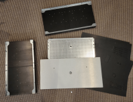
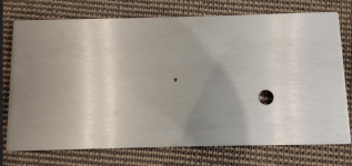
- An illustrated guide to building an F5