Dave-
So I'm sucking on my first cup of Joe, checking the forums, and BAM!..I see this 😀...to cool.
I looked to see "what is this sketchup, of which you speak?"..oh that sketchup. My poor little dial-up is smokin' downloading the proggie now.
Thanx for that..great way to start my day.
-Casey
So I'm sucking on my first cup of Joe, checking the forums, and BAM!..I see this 😀...to cool.
I looked to see "what is this sketchup, of which you speak?"..oh that sketchup. My poor little dial-up is smokin' downloading the proggie now.
Thanx for that..great way to start my day.
-Casey
Hmmmmmmmmmmmm
Well I knew my good friend would come through with a great concept diagram.
Here are a few things to think about now that we have something to look at:
Tweeter alignment. I think you were talking about a long ribbon. That is going to make a very interesting chalenge. You may end up with a real wide baffle.I hopwe you are okay with that.
Bracing: this puppy is going to need some serious cross bracing to keep the side walls from purring like a kitty cat.
You may want to tighten up that bend if you can. It will make the construction a little easier.
Anyway lots of things to start talking about.
I think you were talking about a long ribbon. That is going to make a very interesting chalenge. You may end up with a real wide baffle.
Aprox. 24" at the widest point on a triangular baffle. Thie pic shows the driver centered..it won't be.
Bracing: this puppy is going to need some serious cross bracing to keep the side walls from purring like a kitty cat.
First, this is why I'm going with 1" mdf, and second, Dave drafted that pic based on only the skeletal diagram I posted that I used to sim..my final draft will show the bracing scheme.
You may want to tighten up that bend if you can.
I'm more concerned with keeping the depth top & bot. the same.
-Casey
valveitude said:So I'm sucking on my first cup of Joe.... Thanx for that..great way to start my day.
While having my 1st cup of Turkish. I finished up (well mostly) the plans for a couple dual Extremis 6.8 subs (one a Cube, the other tall, narrow & deep) while i was getting my 1st cup of turkish into my system
http://www.planet10-hifi.com/boxes-other.html (bottom entries)
dave
Way outside the box
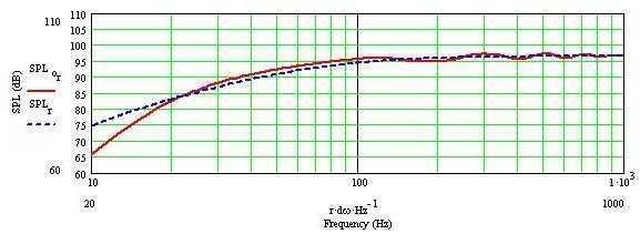
No, I haven't built this...I submit this as an indication of response available from the Extremis.
Using the ML_TQWT worksheet, and the following entries, I get a response with a "knee" below 25 hz and 3 dB down from 150 hz. The response is +/- 1.5 dB from the infinite baffle response above 100hz.
These figures imply a box that is not part of the baffle. The port is so long that it won't fit inside the box. If the port is to have its terminus on a vertical baffle I think they have to be separate.
To use all of the excursion of the Extremis would require a larger diameter port...and be longer still...so I think I'll ask for consideration of this before going further down that road.
L=32 in
Zdriver = 11.25
Zport = 26.5
So = 7.5 x 11
Sl = 7.5 x 11
Density = 0.25 lb/cf
rport = 1.5"
Lport = 22"
graph.
Dave-
That thing looks like it would loosen your fillings 😀.
Ed-
Cool alignment 🙂. I looked at the ML-TQWL alignments about a year ago, and the sure look like the best way to squeeze the last drop of performance out of a driver. I decided, ultimately, to go with a more traditional approach, mainly out of fear of the port. I plan to "glue" the dynamic driver to a dipole ribbon, and my memory of the TL "sound" suggests to me that it would be my best hope at a seemless transition between the two.
You have certainly raised the bar of the possibilities..Thanx for showing that.
-Casey
Re: Way outside the box
The 2nd of the 2 designs i posted above has a port just a bit over 18", how i integrated that into the enclosure would also work for your ML-TL. I'd just slab it on the back,
dave
Ed Lafontaine said:The port is so long that it won't fit inside the box.
The 2nd of the 2 designs i posted above has a port just a bit over 18", how i integrated that into the enclosure would also work for your ML-TL. I'd just slab it on the back,
dave
Hey all,
Egged on by GM, Ed, and others, I went back to work on the Extremis alignment to see how much it could be improved..no small amount as it turns out. After I ran GM's alignment that I posted earlier, I spent the time to draft a an “improved” line that had a smooth transition through the bends. After countless hours of juggling numbers so that 1) the transition through the curves fit the rest of the line,2) the final depth of the bottom matched the top, and 3) all the measurements fell into standard fractions of an inch..what a PITA.
After all that I carefully modeled the results with no less than 19 sections. You can imagine my grief when no matter what I did with the stuffing, I couldn't match my earlier attempt, let alone the graph GM posted. I went back to my first attempt at a 8->1 line, and right out of the gate it was better..hmmm.
In the process of compensating for the lack of taper in the bends, I had to increase the taper in the major section. This resulted into a “staggered” line. I will leave it to others to explain why, but in this case anyway, it outperforms the “ideal” by no small margin. Encouraged by this, I experimented with more radical compressions, and found that 20->1 produced the best predictions, but as would be expected, the terminus velocity was unacceptable. Taking a page from the port designers, and my first line, I added a flare to the terminus, and then experimented with lengths and tapers of the flare until I arrived at this...
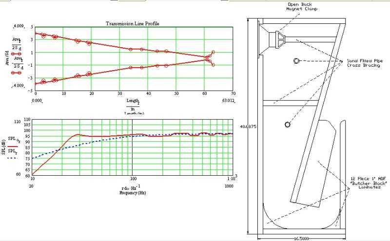
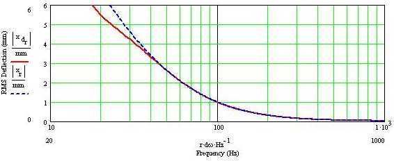
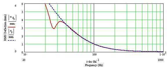
I guess you would call it a TQWP, but I'm not sure that fits. The terminus velocity without the flare looks like this...
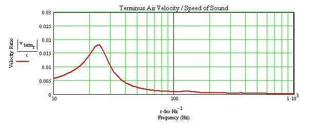
and with it...
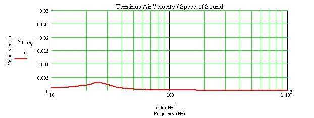
As an added bonus, the expanding section tilts the bottom end response up around 1dB starting at 60hz.
For those that are interested, I posted a PDF of the complete analysis here.
Can anybody see a flaw here that would prevent the predicted performance in “real life”. I'm a little nervous deviating so far from the norm with my first line..but dang..the sims sure look good.
My next challenge is figuring out how to keep the “filling” in place. The posted sim used .33lb^3ft of poly fill from the closed end, to the start of the last bend, and no fill from there to the terminus. Any suggestions on keeping it in place so that it doesn't settle to the bottom?
Dave- please feel free to do another sketchup 😀. I'm trying to learn the proggie, but I'm not there yet.
-Casey
Egged on by GM, Ed, and others, I went back to work on the Extremis alignment to see how much it could be improved..no small amount as it turns out. After I ran GM's alignment that I posted earlier, I spent the time to draft a an “improved” line that had a smooth transition through the bends. After countless hours of juggling numbers so that 1) the transition through the curves fit the rest of the line,2) the final depth of the bottom matched the top, and 3) all the measurements fell into standard fractions of an inch..what a PITA.
After all that I carefully modeled the results with no less than 19 sections. You can imagine my grief when no matter what I did with the stuffing, I couldn't match my earlier attempt, let alone the graph GM posted. I went back to my first attempt at a 8->1 line, and right out of the gate it was better..hmmm.
In the process of compensating for the lack of taper in the bends, I had to increase the taper in the major section. This resulted into a “staggered” line. I will leave it to others to explain why, but in this case anyway, it outperforms the “ideal” by no small margin. Encouraged by this, I experimented with more radical compressions, and found that 20->1 produced the best predictions, but as would be expected, the terminus velocity was unacceptable. Taking a page from the port designers, and my first line, I added a flare to the terminus, and then experimented with lengths and tapers of the flare until I arrived at this...
I guess you would call it a TQWP, but I'm not sure that fits. The terminus velocity without the flare looks like this...
and with it...
As an added bonus, the expanding section tilts the bottom end response up around 1dB starting at 60hz.
For those that are interested, I posted a PDF of the complete analysis here.
Can anybody see a flaw here that would prevent the predicted performance in “real life”. I'm a little nervous deviating so far from the norm with my first line..but dang..the sims sure look good.
My next challenge is figuring out how to keep the “filling” in place. The posted sim used .33lb^3ft of poly fill from the closed end, to the start of the last bend, and no fill from there to the terminus. Any suggestions on keeping it in place so that it doesn't settle to the bottom?
Dave- please feel free to do another sketchup 😀. I'm trying to learn the proggie, but I'm not there yet.
-Casey
how to keep the “filling” in place
Casey, You are covering a lot of ground.
Your cross bracing is a good idea, and will help with this.
There is a material called "tulle" which is used in costumes. It is a very light, open weave material. I think it could be stapled to the inside of your casework forming as many compartments as you need. That's what I'm gonna do...raid the better half's fabric stash.
I, like you, have labored over attaining a "flat" response only to be disappointed by the fat bass the came out. It is not well defined...room gain does exist...and estimates vary. Your room has everything to do with it. Small and closed will provide more lift. Large and open -> less lift.
I have found with ML-QWT's that I can get rid of the bump right above the knee in the response by decreasing the x-sectional area. I don't know if this holds true for tapered lines. YMMV.
Hi Ed,
Awesome 🙂. That is a fantastic suggestion. I was thinking "nylons" filled with batting, but this stuff sounds a lot better...thank you. I don't suppose you could spell it phonetically for me..I don't want to look like a total tool in the store.
Well ya. The curve you posted was a primary reason I hit the keyboard again 🙂.
When GM posted his alignment, I got a lot of feedback (here and email) that I would be well advised to follow it. If you overlay mine and his, other than another 10hz of extension, they are practically identical. Room gain is always a concern, in my case the major node appears to be in the 100-200hz region. Of course, it could always sound like poo anyway, I guess I'll find out.
-Casey
There is a material called "tulle" which is used in costumes....
Awesome 🙂. That is a fantastic suggestion. I was thinking "nylons" filled with batting, but this stuff sounds a lot better...thank you. I don't suppose you could spell it phonetically for me..I don't want to look like a total tool in the store.
I, like you, have labored over attaining a "flat" response...
Well ya. The curve you posted was a primary reason I hit the keyboard again 🙂.
...only to be disappointed by the fat bass the came out.
When GM posted his alignment, I got a lot of feedback (here and email) that I would be well advised to follow it. If you overlay mine and his, other than another 10hz of extension, they are practically identical. Room gain is always a concern, in my case the major node appears to be in the 100-200hz region. Of course, it could always sound like poo anyway, I guess I'll find out.
-Casey
Ed Lafontaine said:I, like you, have labored over attaining a "flat" response only to be disappointed by the fat bass the came out. It is not well defined...room gain does exist...and estimates vary. Your room has everything to do with it. Small and closed will provide more lift. Large and open -> less lift.
You echo my exact thoughts as i was looking at that FR ... i expect you'll be stuffing the terminus, adding some EQ in the botom to counter the room gain, or just moving the whole hif outside....
... and to compound that i just came from looking at a sim for a dual extremis Nagaoka-style BVR that Scott did to be a match to the Calhouns. It is a very good example of taking room gain into consideration. The FR does not look a whole lot different than a sealed box, but from the excursion plot you can see that it has a whole lot more capability in the 20-40 Hz range. The low Q should give good tight bass, the excursion capabilities extended by the horn should give then a whole lot of punch.
Even so, can you post (or send me a larger version of the drawing?)
dave
PS with an anechic F10 of 20 Hz, in room it should be pretty much flat to 20, maybe lower in the right room.
Attachments
Renron said:
"rock wool"aka "slag wool"
But I do know about Rock Wool, many years ago when I rode dirt bikes we would stuff the mufflers with rock wool when they got too loud or lost back pressure.
Best luck,
Ron
You mean when you lost velocity, not backpressure. 😉
Hi Dave,
A fella just can't win
My main thrust here, was to get a smooth response with as little stuffing as possible as a starting point. My brother and I went over the plan today, and we are going to set up the cabs so that one side is easily rmovable. This is needed to access the clamp that will hold the cross bracing pipe to the driver for speaker removal, and, to your point, making fine tuning the stuffing easier...you can always cut bass output, getting more isn't so easy. By adding stuffing in the last leg, the response starts tipping down, much like the gaph you posted.
Bottom line..you can always take the low end away by "corking" the line.
I attached a Windows Meta File in zip.
Yes, that is exactly what I mean 😉. I want the backressure.
-Casey
You echo my exact thoughts as i was looking at that FR ... i expect you'll be stuffing the terminus, adding some EQ in the botom to counter the room gain, or just moving the whole hif outside....
A fella just can't win
My main thrust here, was to get a smooth response with as little stuffing as possible as a starting point. My brother and I went over the plan today, and we are going to set up the cabs so that one side is easily rmovable. This is needed to access the clamp that will hold the cross bracing pipe to the driver for speaker removal, and, to your point, making fine tuning the stuffing easier...you can always cut bass output, getting more isn't so easy. By adding stuffing in the last leg, the response starts tipping down, much like the gaph you posted.
Bottom line..you can always take the low end away by "corking" the line.
Even so, can you post (or send me a larger version of the drawing?)
I attached a Windows Meta File in zip.
You mean when you lost velocity, not backpressure.
Yes, that is exactly what I mean 😉. I want the backressure.
-Casey
Attachments
Dave & Ed-
You started me questioning myself again (I'm too easy a target😉), so i ran the sim with .75lb ft^3 off stuffing in the last leg of the line (currentl empty), and this is what I got...
😀 😀 😀
You can always throttle back, but when your outa steam, your outa steam.
I should be able to "season to taste" with this design quite readily.
-Casey
Looks good.... What is the excursion like?
Also, can you give me a reference dimension on the drawing? Once i got it into the CAD program it was ~18" high
dave
Also, can you give me a reference dimension on the drawing? Once i got it into the CAD program it was ~18" high
dave
Looks good.... What is the excursion like?
Not as good as it does without the stuffing, but I believe it's livable. This is with 10W in...
Also, can you give me a reference dimension on the drawing?
My bad...I exported the wrong draft. The dimensions are 40.6250"(40 11/16ths) high by 14" wide by 16.5" deep. All material is 1" thick.
-Casey
valveitude said:You can always throttle back, but when your outa steam, your outa steam.
Bottom line..you can always take the low end away by "corking" the line.
Greets!
Yep, this is my philosophy! Acoustic solutions to acoustic problems. You can also 'gap' the driver away from the baffle slightly and add a felt or similar gasket if need be to fine tune it.
GM
I must be getting tired..I forgot to post the excursion at it's default tuning for comparison...
Stuffing the terminus cuts back on the excursion dampening..well a lot of stuffing like I did above anyway. Truthfully, I doubt I would put that much in. I would be more inclined to put a simple R/C network to the power amp at line level if I really need to cut the bass.
-Casey
Stuffing the terminus cuts back on the excursion dampening..well a lot of stuffing like I did above anyway. Truthfully, I doubt I would put that much in. I would be more inclined to put a simple R/C network to the power amp at line level if I really need to cut the bass.
-Casey
Hi GM-
Seems we were posting at the same time 🙂
Thats an excellent tip..thank you. I wasn't as clear as I meant to be in my last post..I meant to say I would put a roll off filter on the power amp if a "reasonable" amount of stuffing (no more than .5lb ft^3 in the terminus) didn't cut it enough. You just gave me another tool to avoid that.
-Casey
Seems we were posting at the same time 🙂
You can also 'gap' the driver away from the baffle slightly and add a felt or similar gasket if need be to fine tune it.
Thats an excellent tip..thank you. I wasn't as clear as I meant to be in my last post..I meant to say I would put a roll off filter on the power amp if a "reasonable" amount of stuffing (no more than .5lb ft^3 in the terminus) didn't cut it enough. You just gave me another tool to avoid that.
-Casey
- Status
- Not open for further replies.
- Home
- Loudspeakers
- Multi-Way
- An Extremis 6.8 Offset Reducing Taper TL Design