Hi ypasco
An apology is wholly unnecessary 🙂. You didn't try to mislead, rather it was a misunderstanding. If I had to say "sorry" everytime I read something wrong, my s.o.r,and y keys would have holes wore in them 😀.
-Casey
your design sounds good to me now... i apologize...
An apology is wholly unnecessary 🙂. You didn't try to mislead, rather it was a misunderstanding. If I had to say "sorry" everytime I read something wrong, my s.o.r,and y keys would have holes wore in them 😀.
-Casey
Ok..stole a few minutes at lunch to run a few sims.
The 8->1 alignment that GM suggested appears to function much better (is anybody suprised?), on "paper" anyway. I'll have to play around a bunch more before I "finalize". Thanx GM.
-Casey
The 8->1 alignment that GM suggested appears to function much better (is anybody suprised?), on "paper" anyway. I'll have to play around a bunch more before I "finalize". Thanx GM.
-Casey
Greets!
You're welcome!
'zdriver' is what MJK called the driver acoustic center location along the pipe's length on his later freeware sheets. Anyway, for 8:1 CR I typically put the driver up right at the top and 3" is a bit > the Sd radius, so the flange may overlap the top plate thickness, but it can be moved down to allow for a grill if need be.
The 1.0 lb/ft^3 'wad' is in the PORTED WS section Lo0.
The 1" acoustic fiberglass I typically use is much more dense than polyfil, so only a fraction of it is required, but it would take a MJK or similar to program its properties into the WSs to determine the differences.
Even if the room is boosted in the mid-bass, it's usually beneficial as long as it's not so much that it makes tenors sound like sopranos.
Modeling the same doesn't necessarily equate to sounding the same in some cases, especially WRT damping since how it loads the back of the diaphragm can differ enough to be audible. If XO'd while the driver is still mostly a point source, then I doubt it matters much, but with wide BW drivers it does, so you want the least amount of stuffing that damps any eigenmodes (standing waves) between parallel surfaces and/or the driver, then damp any excessive pipe modes separately, usually by adding as much as required at the closed end, though in this case the driver's there, so I shifted it to just below. Also, increasing the taper up to a point not only shortens the line length for a given Fp, but more rapidly decays the vent's harmonics to boot. IOW, the inverse of a horn, so if you want some serious loading use a hyperbolic flare.
GM
Hey GM,
I only have a few minutes (break at work), so this will be shorter than I would like.
Um..I knew that . Actually, since I will be using 1" mdf, I wouldn't have to move it unless I wanted to. I will draft up an outline with this alignment when I get home tonight and play around.
Well, it can be pretty ugly 🙁. A large contributor is my wifes big 'ol oak entertainment center the speaks straddle...I'm workin' on it.
What specfically do you use?
Gotcha..the plan (hope) is that I'll be rolling it off long before it stops acting as a point source (around 300hz), but my brother who has decided he wants to build a pair for himself, at the same time he helps with mine, want's too two way into a dome...I suscpect this is a bigger issue with the "fullranger" types 😉.
You've given me a lot to think about..thanx.
-Casey
I only have a few minutes (break at work), so this will be shorter than I would like.
'zdriver' is what MJK called the driver acoustic center location along the pipe's length on his later freeware sheets. Anyway, for 8:1 CR I typically put the driver up right at the top and 3" is a bit > the Sd radius, so the flange may overlap the top plate thickness, but it can be moved down to allow for a grill if need be.
Um..I knew that
. Actually, since I will be using 1" mdf, I wouldn't have to move it unless I wanted to. I will draft up an outline with this alignment when I get home tonight and play around.Even if the room is boosted in the mid-bass, it's usually beneficial as long as it's not so much that it makes tenors sound like sopranos.
Well, it can be pretty ugly 🙁. A large contributor is my wifes big 'ol oak entertainment center the speaks straddle...I'm workin' on it.
The 1" acoustic fiberglass I typically use is much more dense than polyfil, so only a fraction of it is required, but it would take a MJK or similar to program its properties into the WSs to determine the differences.
What specfically do you use?
Modeling the same doesn't necessarily equate to sounding the same in some cases, especially WRT damping since how it loads the back of the diaphragm can differ enough to be audible. If XO'd while the driver is still mostly a point source...Also, increasing the taper up to a point not only shortens the line length for a given Fp, but more rapidly decays the vent's harmonics to boot. IOW, the inverse of a horn, so if you want some serious loading use a hyperbolic flare.
Gotcha..the plan (hope) is that I'll be rolling it off long before it stops acting as a point source (around 300hz), but my brother who has decided he wants to build a pair for himself, at the same time he helps with mine, want's too two way into a dome...I suscpect this is a bigger issue with the "fullranger" types 😉.
You've given me a lot to think about..thanx.
-Casey
Greets!
You're welcome!
?? The only 1" acoustic fiberglass I know of, what's used to damp HVAC ducts, acoustic tiles, etc..
GM
You're welcome!
?? The only 1" acoustic fiberglass I know of, what's used to damp HVAC ducts, acoustic tiles, etc..
GM
GM-
O-o-h-h-h..gotcha, I wasn't picturing it before. I thought you might have meant something a bit more "rare" 😉.
What exactly are the desired properties of a material for TL stuffing? I have read many suggestions (long hair wool,etc.), but have not read a good explaination of exactly what the desired properties are. One material that has occured to me to try, is "rock wool" aka "slag wool". I made some acoustic absorbtion panels out of this stuff, and they were acoustic "black holes". I was tipped off to this stuff in a small side column in a "Speaker Builder" mag years ago. They ran a comparison, and this stuff was more effective than Sonex panels, as far as absorbtion goes.
Thoughts?
-Casey
?? The only 1" acoustic fiberglass I know of, what's used to damp HVAC ducts, acoustic tiles, etc..
O-o-h-h-h..gotcha, I wasn't picturing it before. I thought you might have meant something a bit more "rare" 😉.
What exactly are the desired properties of a material for TL stuffing? I have read many suggestions (long hair wool,etc.), but have not read a good explaination of exactly what the desired properties are. One material that has occured to me to try, is "rock wool" aka "slag wool". I made some acoustic absorbtion panels out of this stuff, and they were acoustic "black holes". I was tipped off to this stuff in a small side column in a "Speaker Builder" mag years ago. They ran a comparison, and this stuff was more effective than Sonex panels, as far as absorbtion goes.
Thoughts?
-Casey
Well now..I just spent the last couple of hours attempting to draft an 8->1 line, per GM's alignment. I have come to the conclusion there are 3 options. 1) A straight line, putting the driver at top or bottom 2) Bending into a funky looking "L" to place the driver in the right position regarding the planned ribbon. 3) Acquire a great deal more skill than I have to fold it into a backwards exponential “horn”.
I concede that the GM alignment looks better in the worksheet, but realizing it for my application just isn't practical. I spent over a year now “gilding the Lilly” in my turntable project, I really don't want to repeat that here. If the 3dB dip at 120hz in my alignment is an issue after the baffle and room slings the response all over the map, then I'll sneak a little correction in to it's dedicated amp. As for the allure of the added compression of the steeper line requiring less stuffing, not a real issue for me as the line will be cut off before it hits the area that would benefit from the reduction (300hz). Maybe for my brother, I'll point him to this thread and let him decide.
In short, I bow to thee Mr. GM , but I'm going with my plan A.
-Casey
I concede that the GM alignment looks better in the worksheet, but realizing it for my application just isn't practical. I spent over a year now “gilding the Lilly” in my turntable project, I really don't want to repeat that here. If the 3dB dip at 120hz in my alignment is an issue after the baffle and room slings the response all over the map, then I'll sneak a little correction in to it's dedicated amp. As for the allure of the added compression of the steeper line requiring less stuffing, not a real issue for me as the line will be cut off before it hits the area that would benefit from the reduction (300hz). Maybe for my brother, I'll point him to this thread and let him decide.
In short, I bow to thee Mr. GM
, but I'm going with my plan A. -Casey
valveitude said:GM-
O-o-h-h-h..gotcha, I wasn't picturing it before. I thought you might have meant something a bit more "rare" 😉.
What exactly are the desired properties of a material for TL stuffing? I have read many suggestions (long hair wool,etc.), but have not read a good explaination of exactly what the desired properties are. One material that has occured to me to try, is "rock wool" aka "slag wool". I made some acoustic absorbtion panels out of this stuff, and they were acoustic "black holes". I was tipped off to this stuff in a small side column in a "Speaker Builder" mag years ago. They ran a comparison, and this stuff was more effective than Sonex panels, as far as absorbtion goes.
Thoughts?
-Casey
"rock wool"aka "slag wool"
This is just about the only thing I have understood in this entire thread.
 Being an ULTRAnoob at this whole speaker building thing, inc. xovers
  , But I do know about Rock Wool, many years ago when I rode dirt bikes we would stuff the mufflers with rock wool when they got too loud or lost back pressure. It sounds like the perfect sound deadening material.
 I am seriously concidering build a SMALL Thor set, and am trying to learn as much as I can. The TL design(s) seems to drawn my attention much more than other designs.
Best of luck with your design. Looks to me like you have a winner here.
Best luck,
Ron
Gm design TQWP
Hello valveitude:
The design that GM put forth for you is not that complicated. It is simply a rectangular cone with the driver as close to the big end as possible. If you were to use a 10 inch inside width dimension it would taper from 17 3/8 to 2 inches over a 56.5 in length. This wedge can be folded pretty much any where you like. Typically you fold the pipe so that driver is located approx 36 inches off the floor in the finished design. So make a right triangle and fold it. The tricky part is going around the inside corner. I am sure my good friend Planet10 has a nifty program to help with the corner bend and can make a very nice diagram.
The only factor I have not seen yet is the port location or dimension.
Thanks for the interesting threads. A word of help. Listen to GM he designs real nice stuff. I have made a few of his designs and he does know his stuff.
Good luck
Hi SCD,
Of this, there is little doubt 🙂
When I made my last post, I was frustrated, tired, and just a wee bit cranky. I started thinking about it again, and I will give GM's alignment another go. For ease of construction, I was hoping to keep the geometry simple by limiting the cuts to what could be done with a table saw and circle cutter..that just aint happening with the 8->1 alignment.
Is Planet 10's program posted anywhere, or do I need to email him?
Thanx,
Casey
A word of help. Listen to GM he designs real nice stuff. I have made a few of his designs and he does know his stuff.
Of this, there is little doubt 🙂
When I made my last post, I was frustrated, tired, and just a wee bit cranky. I started thinking about it again, and I will give GM's alignment another go. For ease of construction, I was hoping to keep the geometry simple by limiting the cuts to what could be done with a table saw and circle cutter..that just aint happening with the 8->1 alignment.
Is Planet 10's program posted anywhere, or do I need to email him?
Thanx,
Casey
Hello Casey:
I would E-mail P10 directly.
I think a table saw, a jig saw, a router and few hand tools are pretty much all you need to make the cabinet. There are many examples of folded TWQP to help conceptualise the design.
I do not have access to any fancy programs so I just sketch my plans up on a paper.
I am sure Dave will be along in a few hours to offer a bit of comment and help. If you look at his web page you will find all sorts of intersting presentations styles.
I hope this helps
Hi Dave,
I dunno
SCD suggested you had one to handle the geometry of bends in a tapered pipe.
-Casey
drawing program?
I dunno
SCD suggested you had one to handle the geometry of bends in a tapered pipe.
-Casey
valveitude said:you had one to handle the geometry of bends in a tapered pipe.
There was a paper done by one of the guys in Vancouver, that does exact math for a tapered line where the corners are radused. I usually just use the BIB approximation and don't wander far from the root2:1 ratio.
dave
Dave-
No worries..I think I landed on a cabinet configuration I can live with.
I'll run it up in cad tonight, and check it out.
-Casey
No worries..I think I landed on a cabinet configuration I can live with.
I'll run it up in cad tonight, and check it out.
-Casey
Simple methods for calculating bend geometry in a tapered tube
By: M. Jensen Didulo
Date: 11 December 2003
Revision: 1.1
http://p10hifi.net/planet10/TLS/downloads/TL-bend-geometry.pdf
dave
By: M. Jensen Didulo
Date: 11 December 2003
Revision: 1.1
http://p10hifi.net/planet10/TLS/downloads/TL-bend-geometry.pdf
dave
Planet10-
Thanx!! I've got some readin' to do 🙂
GM-
Alrighty then..cooler heads prevailed, and I have decided to follow your advice, and go with your alignment (to the best of my abilities anyway). The piece that nudged me over the line was some prelim baffle step calculations. I can now see why you didn't care for the dip in my alignment.
Anyhoo, this is where I have gotten so far...
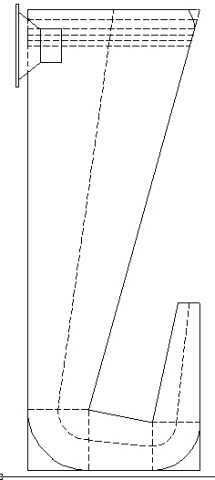
I drew this before I saw planet10's link, so the bends don't have the taper. Consequently, I had to scab a couple of inches on the end to compensate. It's not perfect, but it is close. After dinking with the stuffing a bit, this is the curve I got so far...
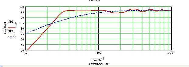
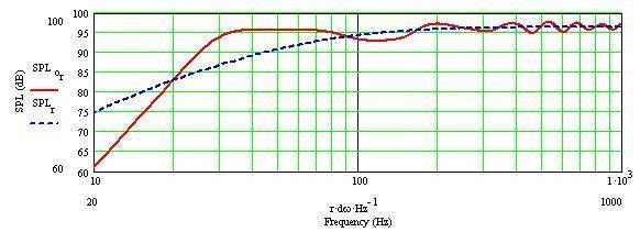
For comparison, here's the earlier alignment...
After studying the linked paper a bit, I'll attempt to improve it by getting the taper in the bends.
And this was supposed to be a quick diversion from my table project...sheesh.
-Casey
Thanx!! I've got some readin' to do 🙂
GM-
Alrighty then..cooler heads prevailed, and I have decided to follow your advice, and go with your alignment (to the best of my abilities anyway). The piece that nudged me over the line was some prelim baffle step calculations. I can now see why you didn't care for the dip in my alignment.
Anyhoo, this is where I have gotten so far...
I drew this before I saw planet10's link, so the bends don't have the taper. Consequently, I had to scab a couple of inches on the end to compensate. It's not perfect, but it is close. After dinking with the stuffing a bit, this is the curve I got so far...
For comparison, here's the earlier alignment...
After studying the linked paper a bit, I'll attempt to improve it by getting the taper in the bends.
And this was supposed to be a quick diversion from my table project...sheesh.
-Casey
can you put some dimensions on that?
This is just a skelatal outline to work out the modeling..but it's real close.
I'll post a detailed drawing when I taper the bends, and finalize the overall taper (tomorrow evening if all goes well). The overall dimensions shouldn't change though. Excluding wood thickness, it's 38 5/8” H x 12”W x14 1/2” D., the driver center is 3” down from the top. I plan on 1” mdf, so figure 2” additional each dim.. The design length down the center line is 56.46”. Like I said above though, I “scabbed” a few inches on the open end to compensate for the lack of taper in the bends...in the worksheet that is, not the drawing.
-Casey
- Status
- Not open for further replies.
- Home
- Loudspeakers
- Multi-Way
- An Extremis 6.8 Offset Reducing Taper TL Design