I needed something easy and convenient to control the sound system of my living-room: it is basically connected to the TV, but I also plug in an occasional device, like a laptop, player, tablet....
I wanted the thing to be completely transparent and automatic: no manipulation whatsoever, be it soft or hard.
The amplifier is a multichannel class AB, and thus consumes a non-negligible of quiescent power, meaning it has to be switched off when not in use.
The SelfSel takes care of all of that: it connects the active source to the amp, and switches it on as soon as a signal is detected.
Of course, it handles all of the subsidiary details, like timings, priority, persistence, etc.
An important warning:
In its current form, it is not ideal, and may not be suited to all situations.
I kept it that way, simply because it works for me, and I don't see the need to make mods just for the beauty of it, but if I made a 2.0 version, it would be somewhat different.
Later, I will try to alter the 1.0 version to make the project more universal, but it will be a purely theoretical exercise, since I have no intention of rebuilding mine, or building another one.
The circuit is not complex from a component count perspective, but it looks rather complicated, because it extracts a maximum of functions from a minimal number of devices.
It looks a bit like TV "jungle" circuits of the early seventies, with a mix of linear, digital, power and timing circuits.
It does work perfectly smoothly though, and is perfectly well-behaved.
Its only weakness is a lowish sensitivity: it requires about 100mV for a valid detection.
With modern, digital sources delivering 0.7V, 1V or even more, that's not a problem, because the 100mV level only needs to be present a few ms every 1~2 minutes, which is easily achieved.
With older AUX-level sources of 250mV or even less, there would certainly be problems.
The problem stems from a mis-evaluation and from the low gain of CMOS inverters:
Initially, the circuit was designed with a dual opamp frontend, but I figured out that with a little ingenuity, I could dispense with it, and use two CMOS gates as amplifiers.
The total supply voltage was 12V, and I didn't feel the need to change it: it allowed a very robust signal-handling capability.
However, CMOS gates have their OL gain drop quickly with increasing supply voltage, and at 12V, it is only 15~20.
I thought it was going to be enough, and I was right -sort of-, but even with line levels, I felt the need to push the gain trimmers to the max, not something ideal.
This means that the circuit, in its current published form should just be a source for inspiration, and should not be duplicated exactly.
Attachments


How it works:
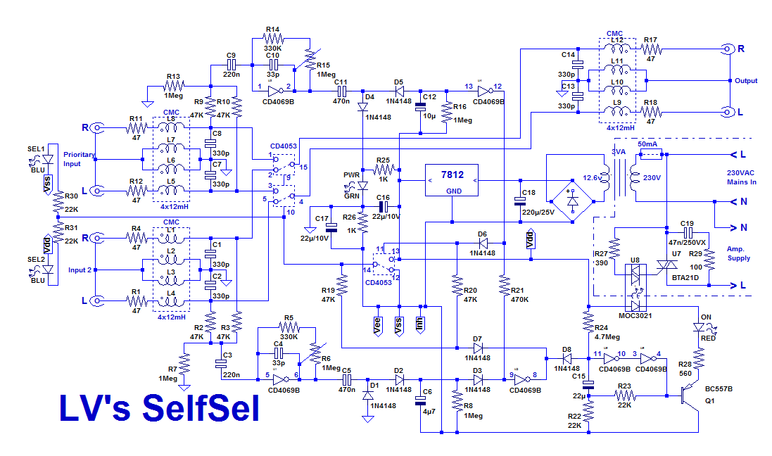
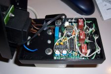
The input signals first pass through common-mode chokes. They are not strictly necessary, but I have included them as a precaution, because the box is at the junction between a number of devices, most of them class II and using switching supplies, with cables several meters long, all of which can typically cause common-mode issues.
I wanted it to be dead quiet, and it succeeded.
The CMC's are 4-way types, because the 3-way variety is much less common.
After the CMC's, the signals go to the switches and to the vox circuits, via a resistive mixer (R9 & R10 f.e.).
A CMOS inverter amplifies the signal, which is then rectified by D4, D5.
The rectifier is referenced to a potential shifted positively from the GND by the power LED. D4 and D5 also contribute to the shift, making the quiescent output potential comfortably higher than the threshold voltage of the threshold detecting gate.
This is necessary, because of the wide dispersion possible with CMOS gates.
The other channel works similarly, but with the polarity (and the shifting) reversed: this is necessary, because the spare 4053 used as a flip-flop does not have separate S and R inputs.
When a signal is detected on one of the channels, it flips the memory-4053, and the signal from its output 14 is used to steer the corresponding input to the output through the two SPDT operators.
When no signal is present, the switches remain in the last active position.
When a signal is detected, it also triggers a one-shot thanks to the diode gate R21-D3 adding the two channels.
The timing components, R24, C15 provide an ON-time of ~1.5 minute.
It can be easily altered if required.
The output of the one-shot drives a MOC3021 optocoupler via Q1.
The MOC drives the control triac.
I have opted for a triac, because I preferred to avoid mechanical relays and their clicking, but a conventional relay can be connected to the emitter of Q1 instead: it is just a matter of taste.
When a signal is present on both channels simultaneously, the logic forces the upper channel selection.
The relative values of the timing components are also designed to ensure a clean, stutter-free operation in this case.
The power path is unfused, because it is unipolar and thus presents no safety hazard, and a fuse capable of effectively protecting the triac would be more expensive than the component it protects....
Here is the version 2.0 (not physically tested):
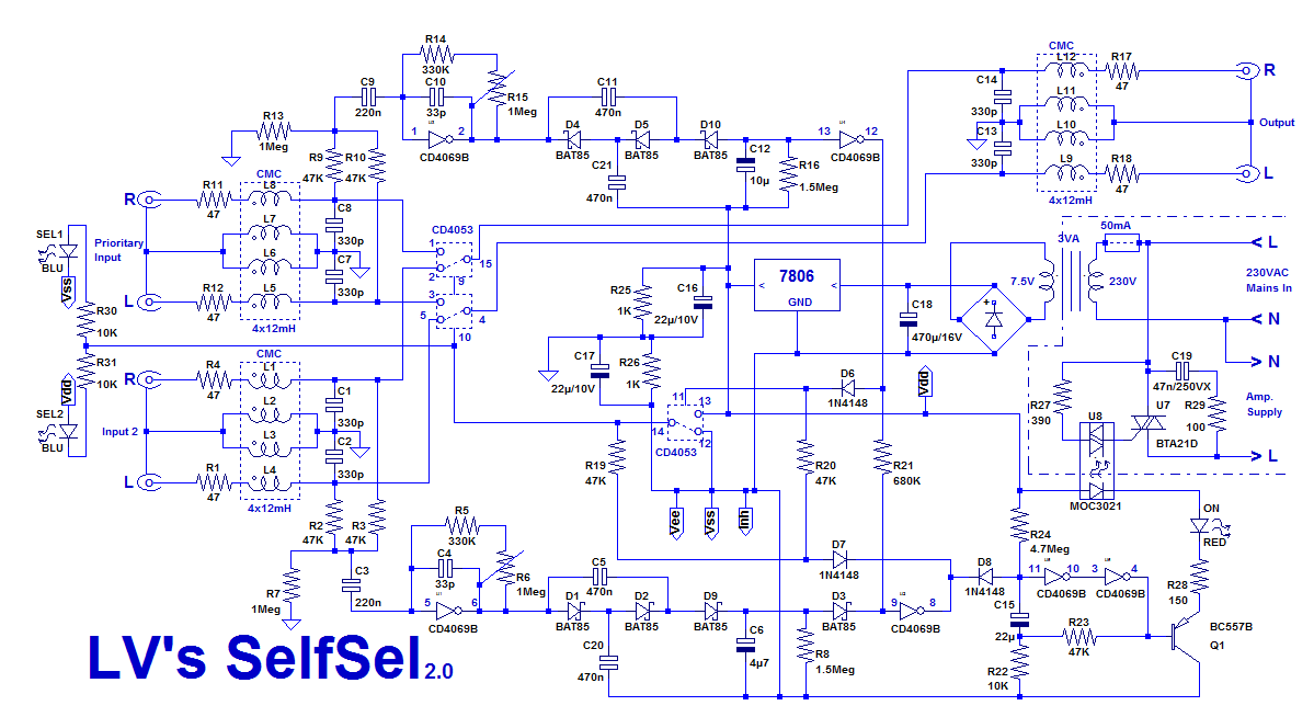
The changes affect mainly the supply voltage and the signal detection section; I have also rationalized a few other details.
Now, the detectors are based on voltage triplers: they not only offer a slightly higher output but more importantly, they are inherently referenced to the average DC level of the amplifiers.
This means that no additional threshold shifting is necessary, because the diodes alone suffice: since the 6 operators of the package have a good matching and tracking, additional margins are no more necessary making a much tighter detection possible.
To take advantage of this automatic compensation, the diodes can be small schottky's, to minimize the excursion necessary for signal detection.
With the improved gain and the lower thresholds, a signal of less than 10mV is now sufficient for a valid detection: I have made a real breadboard test to confirm it.
This is much more comfortable, even with AUX-level sources, and with 6V of total supply, a signal of more than 2Vrms can still be handled safely.
If this is not sufficient, the supply voltage can be adapted: with the triplers, the sensitivity will remain decent.
The power LED has disappeared in the process, but it is easy to add one, and anyway, one of the selection LEDs is always on, meaning it is in fact redundant.
Attachments
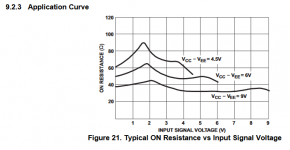
It's a very nice solution. A short question though about the v2.0. Is it a good idea to reduce the supply voltage to the cd4053 to 6V ? ron goes up and vary significantly at lower voltages and distortion with it.
Modern versions of the 4053 are available with much less on-resistance, for instance 74HC4053M96It's a very nice solution. A short question though about the v2.0. Is it a good idea to reduce the supply voltage to the cd4053 to 6V ? ron goes up and vary significantly at lower voltages and distortion with it.
You are right of course, and even with 12V or 15V supplies, purists will still find the added dist. objectionable (I would, if this system was destined to something else than reproducing everyday, run-of-the-mill sources of moderate quality in a less than ideal environment)..Is it a good idea to reduce the supply voltage to the cd4053 to 6V ? ron goes up and vary significantly at lower voltages and distortion with it.
It can be improved, and Mark gave a possibility.
If this is not sufficient, you can always stack a number of 4053 (or HC4053) on top of each other, in a double-decker London buses fashion, to reduce the resistance: it works well, because the 4053 have only combinatorial parts, and no sequential ones.
For a casual use, it is perfectly sufficient though: amplifiers generally have an input impedance >10K, making the added distortion tolerable.
There are better options now: many analog switches have a resistance in the ohm range, and there might even be some that mimic the function and pinout of the 4053, but I didn't search in that direction: I wanted to stick with absolute commodity parts, which the 4000 series is (despite being theoretically obsolete)
If you need top quality, electromechanical relays are difficult to beat, and it wouldn't be difficult to adapt one in this case: you just need a buffer transistor.
Since two 4053 operators would become unemployed, they could probably be repurposed and paralleled to drive a small, sensitive DPDT relay
Then there's the brute-force approach, buffer each input, convert it to a current, switch the currents with any old analog switch chip, then convert the current back to a voltage. The resistance variations cannot distort a current signal.
Its rather complex though, and you need to switch unused inputs to ground to avoid them clipping crazily with no load. The current->voltage conversion needs to be done at a low enough impedance to prevent capacitive pickup by the current signal (ie the current needs to be large enough, which imposes a constraint on the maximum on-resistance of the switches).
Its rather complex though, and you need to switch unused inputs to ground to avoid them clipping crazily with no load. The current->voltage conversion needs to be done at a low enough impedance to prevent capacitive pickup by the current signal (ie the current needs to be large enough, which imposes a constraint on the maximum on-resistance of the switches).
A voltage follower right after the 4053 could also help. The on resistance then still varies with signal, but as there is practically no signal current flowing through the switch, the voltage drop across the varying on resistance is reduced.
By the way, it took me a while before I noticed that there is a negative supply, as there should be with a 4053; I had overlooked the fact that the midpoint between R25 and R26 is ground.
By the way, it took me a while before I noticed that there is a negative supply, as there should be with a 4053; I had overlooked the fact that the midpoint between R25 and R26 is ground.
Yes, a buffer alone would be sufficient to eliminate any non-linearity induced distortion: the ON part of the switch (100 to 500 ohm, depending on supply voltage) will be just loaded by some parasitic capacitances, perhaps ~20pF in total, forming a low-pass filter having a cutoff frequency in the tens of MHz, totally irrelevant for the audio range.
Any further complication like V-I conversion, etc. would likely result in a higher distortion.
I didn't include a buffer, because it is a MiFi application in my case, and buffers would add limitations of their own: in practice, the CD4053's can handle signals between Vee-0.5V and Vdd+0.5V, something that even the best R-to-R opamp cannot match
Thanks for all the info. D. Self has some more information on switching with cmos gate in his small signals book. Still, Mark's first solution is probably more than sufficient. Thanks for alerting me to the existence of these chips.
Attached is the figure from the TI datasheet for their HC version.
Attached is the figure from the TI datasheet for their HC version.
Attachments
- Status
- Not open for further replies.
- Home
- Source & Line
- Analog Line Level
- An automatic source & power controller