So I've recently stumbled across DIY electrostatics, and thought they were very cool. I immediately got to the process of building my own pair of electrostatic headphones, guided by DIY Electrostatic Headphones. – HeadWize Memorial. I've researched several threads on forums such as this one, where there are many variables to consider including spacer height, stator hole size, etc, but the one which varied the most was the diaphragm coating.
According to the forums, there are many things to consider when choosing a coating for the diaphragm, such as adhesion, and resistance. I have seen many different coatings, ranging from dish soap, to soluble vinyl, to vaporized platinum used in Sennheiser's HE 1 Sennheiser Sennheiser HE 1 - - In 1991 we created the best headphones in the world. We called them Orpheus. Now, we have done it again. The uncompromising philosophy remaining, this is Sennheiser HE 1. In otherworldly sound and timeless beauty. Perfectly engineered. Equipped with unique features and state-of-the-art technology.. But one article that helped my understanding of the requirements for a coating is this, What, No Diaphragm Coating Material ???.
The author writes a great explanation on how "Quad approached the problem as a pure electrostatic problem rather than an electrical problem." The diaphragm coating is supposed to maintain a charge rather than conduct, otherwise the diaphragm would move in a non-linear fashion. Conveniently, there is a list of materials which easily get charged, aka the triboelectric series:
The author states that that any material above polyester would be suffice, and as it turns out, Quad settled with nylon. And nylon is on the positive side of the list, which makes sense.
I couldn't help but notice mylar was on the list, which happens to be what the diaphragm is made out of. So out of sheer curiosity, I made a transducer with no coating, and applied the bias voltage directly to the mylar. This turned out to be somewhat surprising, because sound came out of it, although it was relatively quiet, and gets unstable at normal volumes. I assumed it made sense because a positive bias charge would indeed charge up nylon, but mylar tends to gain a negative charge instead, which explains the results.
This would be to mylar's disadvantage, because the bias supply outputs a positive high dc voltage. So what if we output a negative bias supply voltage instead? All you would have to do, is reverse the diodes on the voltage multiplier to achieve a negative dc voltage:
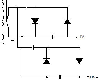
which is what I did, and to my surprise(once again) it actually worked. The bare mylar was able to generate sound, just as if it were positively charged, with a graphite coat. So what is the alternative coating? No coating.
I don't claim to fully understand why this works, only that it worked for me. And since I am making headphones, I'm not sure how this operates on loudspeakers. Feel free to correct me if I misunderstood something.
According to the forums, there are many things to consider when choosing a coating for the diaphragm, such as adhesion, and resistance. I have seen many different coatings, ranging from dish soap, to soluble vinyl, to vaporized platinum used in Sennheiser's HE 1 Sennheiser Sennheiser HE 1 - - In 1991 we created the best headphones in the world. We called them Orpheus. Now, we have done it again. The uncompromising philosophy remaining, this is Sennheiser HE 1. In otherworldly sound and timeless beauty. Perfectly engineered. Equipped with unique features and state-of-the-art technology.. But one article that helped my understanding of the requirements for a coating is this, What, No Diaphragm Coating Material ???.
The author writes a great explanation on how "Quad approached the problem as a pure electrostatic problem rather than an electrical problem." The diaphragm coating is supposed to maintain a charge rather than conduct, otherwise the diaphragm would move in a non-linear fashion. Conveniently, there is a list of materials which easily get charged, aka the triboelectric series:
An externally hosted image should be here but it was not working when we last tested it.
The author states that that any material above polyester would be suffice, and as it turns out, Quad settled with nylon. And nylon is on the positive side of the list, which makes sense.
I couldn't help but notice mylar was on the list, which happens to be what the diaphragm is made out of. So out of sheer curiosity, I made a transducer with no coating, and applied the bias voltage directly to the mylar. This turned out to be somewhat surprising, because sound came out of it, although it was relatively quiet, and gets unstable at normal volumes. I assumed it made sense because a positive bias charge would indeed charge up nylon, but mylar tends to gain a negative charge instead, which explains the results.
This would be to mylar's disadvantage, because the bias supply outputs a positive high dc voltage. So what if we output a negative bias supply voltage instead? All you would have to do, is reverse the diodes on the voltage multiplier to achieve a negative dc voltage:
which is what I did, and to my surprise(once again) it actually worked. The bare mylar was able to generate sound, just as if it were positively charged, with a graphite coat. So what is the alternative coating? No coating.
I don't claim to fully understand why this works, only that it worked for me. And since I am making headphones, I'm not sure how this operates on loudspeakers. Feel free to correct me if I misunderstood something.
Without some data, it's hard to comment constructively. A comparison of output at a constant microphone distance, bias, and drive level for each configuration would be helpful. Comparing a coated diaphragm with and without bias would also ensure that that is functioning properly. Including diaphragm-to-stator distance, driven area, etc. would also be useful.
While I've never tried what you are describing, I have run with bias off, and you certainly get low levels of output that way.
While I've never tried what you are describing, I have run with bias off, and you certainly get low levels of output that way.
I think the explanation is adhesion of humidity to the surface of the diaphragm. Soluble nylon resin does the same.
Yes you are right, I shouldn't have been lazy to provide data. I just did an experiment, although quite unsophisticated, I used my phone as a mic. Coated and non-coated were tested with different biases. The same frequency sin wave was played at the same volume through each trial.
Coated, negative bias:
Non-coated, negative bias:
Coated, no bias:
Non-coated, no bias:
Coated, positive bias:
Non-coated, positive bias:
The results for the coated make sense. Positive or negative bias, it operates at the same level, and barely when there is no bias. However, the results for non-coated made no sense to me at first, because it worked no matter what the bias was, and wasn't even affected when there was no bias. I even made sure to short the bias and the stators for a long time, to ensure there was no potential between the two, for the no bias trials.
This leads me to believe my initial post was wrong, about a negative bias charging the diaphragm. I think a good possibility was that the diaphragm was charged by the friction of my hands when handling it. This would explain why it worked flawlessly with no bias, the high resistance of mylar wouldn't gain or dissipate a charge, even if a conductor was in contact. If this is the case, it would be unfortunate, because theoretically the charge would be slowly lost to the atmosphere, again depending on the resistance of the mylar.
Coated, negative bias:
An externally hosted image should be here but it was not working when we last tested it.
Non-coated, negative bias:
An externally hosted image should be here but it was not working when we last tested it.
Coated, no bias:
An externally hosted image should be here but it was not working when we last tested it.
Non-coated, no bias:
An externally hosted image should be here but it was not working when we last tested it.
Coated, positive bias:
An externally hosted image should be here but it was not working when we last tested it.
Non-coated, positive bias:
An externally hosted image should be here but it was not working when we last tested it.
The results for the coated make sense. Positive or negative bias, it operates at the same level, and barely when there is no bias. However, the results for non-coated made no sense to me at first, because it worked no matter what the bias was, and wasn't even affected when there was no bias. I even made sure to short the bias and the stators for a long time, to ensure there was no potential between the two, for the no bias trials.
This leads me to believe my initial post was wrong, about a negative bias charging the diaphragm. I think a good possibility was that the diaphragm was charged by the friction of my hands when handling it. This would explain why it worked flawlessly with no bias, the high resistance of mylar wouldn't gain or dissipate a charge, even if a conductor was in contact. If this is the case, it would be unfortunate, because theoretically the charge would be slowly lost to the atmosphere, again depending on the resistance of the mylar.
the high resistance of mylar wouldn't gain or dissipate a charge, even if a conductor was in contact. If this is the case, it would be unfortunate, because theoretically the charge would be slowly lost to the atmosphere, again depending on the resistance of the mylar.
It can take hours for dielectric absorption to dissipate in an ESL. When chasing this kind of stuff, I'd typically let a speaker sit overnight to try to get back to a baseline condition. Normally that was enough.
Thanks for following up with the extra tests.