Recently, user Vincent77 has been discussing his preamplifier project that uses LDRs for volume control:
http://www.diyaudio.com/forums/anal...d-ldr-volume-source-selection-controller.html
This got me thinking about just how one could continuously measure the resistance of an LDR while it is in use, in circuit, for instance as an element in a gain stage. After some toying around in my simulator, I came up with something that just might be interesting enough to try...
The idea is to pass DC current through the LDR and measure the resulting voltage drop. The audio signal is AC coupled in and out of this portion of the circuit to isolate it from the DC current. The DC current is supplied from a constant voltage source via a resistor of known value that forms a voltage divider with the LDR, and after some simple algebra one can derive a formula for calculating the resistance if the DC voltage at the junction of the fixed resistor and the LDR is known. Of course the AC audio signal will be present on top of this, so a long term average of the DC voltage must be taken, low-pass filtering used, etc.
When the voltage of the source that supplies current is made to be 5V, the current setting resistor is chosen wisely, and the input voltage to the circuit is assumed to be of limited range (e.g. less than 2Vpk-pk) then the measurement can very conveniently be done via an Arduino input pin, which has very high impedance but can not be subjected to voltages below 0Vdc or above 5Vdc. Once the signal has been acquired by the Arduino, the low pass filtering or other processing can easily be done in software.
In my simulator I set the LDR resistance to a few values between 1k and 100k, recorded the DC voltage across the LDR, and then back calculated the LDR resistance value using the formula I derived earlier. The calculation provided a match to better than 0.25%. This seems very encouraging (see data below).
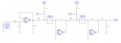
I have attached the circuit diagram. The signal enters at left and is reduced in amplitude via an voltage divider so that the LDR AC signal level is kept low. A buffer isolates the input and drives the next stage where the impedance can be as low as 1k Ohm. The first AC coupling capacitor follows the buffer and then the first LDR. Next we find two inverting gain stages with fixed 1k Ohm feedback resistors and an LDR input resistor. These two gain stages are again separated by an AC coupling capacitor. Separate 5V sources with a resistor serve as a source of DC current through each LDR, draining to the summing point of each ground-referenced inverting gain stage. Note that the second gain stage provide boost enough to provide overall circuit gain at the maximum volume setting of about 10dBv.
A final DC blocking capacitor is used to ensure that the output is AC only. Because there are two inverting gain stages, the circuit is overall non-inverting. If the circuit needs to drive low impedance loads another 5532 output buffer could be added on to the output end prior to the coupling capacitor.
The resistance of each LDR would be set/controlled by current supplied from an Arduino output pin and would vary between 1k and 100k Ohms (100 times) for a total of 80dB of attenuation range.
In the event that no current is supplied to light the LDRs the gain assumes the minimum value and this provides some fault protection for the circuit.
The big question for me is whether the DC current flowing through the LDR resistance cell will increase distortion. I went back and re-read the Perkin-Elmer Vactrol app notes that I have saved and it seems that only the AC voltage level is related to distortion. DC bias itself does not seem to be a source of distortion although this needs to be tested and verified (any volunteers?).
At this point I ask that anyone with a keener sense of circuit design (most of you!) take a look and let me know what you think (good or bad) especially if there are some major flaws that don't show up in a simulator (oops, did I just design another oscillator???). The idea seems interesting to me, and seems like a practical way to continuously monitor (and correct) the LDR resistance using a PIC like the Arduino. Since each channel has two independent LDRs, one would want to keep channel-to-channel tracking as good as possible by trimming the LDR resistances as needed. The drift is likely to be slow, so the long term averaging of the LDR voltage (at TP1 and TP2 in the circuit schematic) should be sufficient. At startup the input signal can be muted so that only the DC current is present and an initial reading can be made. An internal map of the current required to set each LDR to a particular resistance can be saved and updated over time.
.
http://www.diyaudio.com/forums/anal...d-ldr-volume-source-selection-controller.html
This got me thinking about just how one could continuously measure the resistance of an LDR while it is in use, in circuit, for instance as an element in a gain stage. After some toying around in my simulator, I came up with something that just might be interesting enough to try...
The idea is to pass DC current through the LDR and measure the resulting voltage drop. The audio signal is AC coupled in and out of this portion of the circuit to isolate it from the DC current. The DC current is supplied from a constant voltage source via a resistor of known value that forms a voltage divider with the LDR, and after some simple algebra one can derive a formula for calculating the resistance if the DC voltage at the junction of the fixed resistor and the LDR is known. Of course the AC audio signal will be present on top of this, so a long term average of the DC voltage must be taken, low-pass filtering used, etc.
When the voltage of the source that supplies current is made to be 5V, the current setting resistor is chosen wisely, and the input voltage to the circuit is assumed to be of limited range (e.g. less than 2Vpk-pk) then the measurement can very conveniently be done via an Arduino input pin, which has very high impedance but can not be subjected to voltages below 0Vdc or above 5Vdc. Once the signal has been acquired by the Arduino, the low pass filtering or other processing can easily be done in software.
In my simulator I set the LDR resistance to a few values between 1k and 100k, recorded the DC voltage across the LDR, and then back calculated the LDR resistance value using the formula I derived earlier. The calculation provided a match to better than 0.25%. This seems very encouraging (see data below).
Code:
LDR     DCV      backcalc   error
1k      0.4546    1.0001    0.01%
2k      0.8335    2.0005    0.02%
5k      1.665     4.9925    0.15%
10k     2.5       10.000    0.00%
22k     3.435     21.948    0.23%
50k     4.165     49.880    0.24%
100k    4.545     99.890    0.11%
I have attached the circuit diagram. The signal enters at left and is reduced in amplitude via an voltage divider so that the LDR AC signal level is kept low. A buffer isolates the input and drives the next stage where the impedance can be as low as 1k Ohm. The first AC coupling capacitor follows the buffer and then the first LDR. Next we find two inverting gain stages with fixed 1k Ohm feedback resistors and an LDR input resistor. These two gain stages are again separated by an AC coupling capacitor. Separate 5V sources with a resistor serve as a source of DC current through each LDR, draining to the summing point of each ground-referenced inverting gain stage. Note that the second gain stage provide boost enough to provide overall circuit gain at the maximum volume setting of about 10dBv.
A final DC blocking capacitor is used to ensure that the output is AC only. Because there are two inverting gain stages, the circuit is overall non-inverting. If the circuit needs to drive low impedance loads another 5532 output buffer could be added on to the output end prior to the coupling capacitor.
The resistance of each LDR would be set/controlled by current supplied from an Arduino output pin and would vary between 1k and 100k Ohms (100 times) for a total of 80dB of attenuation range.
In the event that no current is supplied to light the LDRs the gain assumes the minimum value and this provides some fault protection for the circuit.
The big question for me is whether the DC current flowing through the LDR resistance cell will increase distortion. I went back and re-read the Perkin-Elmer Vactrol app notes that I have saved and it seems that only the AC voltage level is related to distortion. DC bias itself does not seem to be a source of distortion although this needs to be tested and verified (any volunteers?).
At this point I ask that anyone with a keener sense of circuit design (most of you!) take a look and let me know what you think (good or bad) especially if there are some major flaws that don't show up in a simulator (oops, did I just design another oscillator???). The idea seems interesting to me, and seems like a practical way to continuously monitor (and correct) the LDR resistance using a PIC like the Arduino. Since each channel has two independent LDRs, one would want to keep channel-to-channel tracking as good as possible by trimming the LDR resistances as needed. The drift is likely to be slow, so the long term averaging of the LDR voltage (at TP1 and TP2 in the circuit schematic) should be sufficient. At startup the input signal can be muted so that only the DC current is present and an initial reading can be made. An internal map of the current required to set each LDR to a particular resistance can be saved and updated over time.
.
Attachments
I thought the optimum use of LDR's was in an L pad attenuator. As for distortion, just measure it, the acceptability level is up to you.

I would like to clarify the text and schematic in the first post:
My schematic shows only the "LDR" side (LDR=light dependent resistor) of an "LED-LDR", sometimes known as a Vactrol or optocoupler (an optically coupled LED and photoresistor). These are typically a 4-terminal device, however, my schematic is only depicting the resistive "LDR" side that is used in the audio path.
Examples of the "LED-LDR" devices include:
Silonix NSL-32SR2
Perkin Elmer VTL5C3
.
Three (big) capacitors in signal path ????
Yes, and I may add that they are ELECTROLYTIC capacitors. 😱
Mr. Douglas Self has looked into distortion in DC-blocking electrolytic caps extensively. I can suggest the following reading:
D. Self; Small-Signal Audio Design, Chapter 2 preview
In short, no problemo.
.
Last edited:
DC current through the LDR will bias it and so allow the symmetric distortion characteristic of the LDR to produce asymmetric distortion too. In other words, you will get 2nd as well as 3rd. How much depends on the DC current/voltage: basically in calculating 3rd order distortion you treat the DC as part of the signal so if 1V of AC gives you X% 3rd order then 1V of AC plus 1V of DC will give you X% 2nd too. Whether this is significant depends on the exact application, and the preferences of the listener.CharlieLaub said:The big question for me is whether the DC current flowing through the LDR resistance cell will increase distortion. I went back and re-read the Perkin-Elmer Vactrol app notes that I have saved and it seems that only the AC voltage level is related to distortion. DC bias itself does not seem to be a source of distortion although this needs to be tested and verified (any volunteers?).
I am glad that the thread makes it clear that you are dealing with an LDR; too many people now seem to think that an 'LDR' always comes with an LED attached!
This got me thinking about just how one could continuously measure the resistance of an LDR while it is in use, in circuit,
...
The idea is to pass DC current through the LDR and measure the resulting voltage drop. The audio signal is AC coupled in and out of this portion of the circuit to isolate it from the DC current.
I am pretty sure that would work. But I don't see the point, especially if you're going to use an Arduino or other µP anyway. I feel it's easier to just calibrate each LDR for a number of attenuation levels, stored these calibrations, and determine the LED currents required for a given attenuator setting from these stored calibration data. With a DC voltage superimposed to the audio signal, you'll have to block the DC using capacitors, and make sure the DC is very clean to avoid adding noise to the audio signal. That's doesn't seem like a clean audio signal path to me.
DC current through the LDR will bias it and so allow the symmetric distortion characteristic of the LDR to produce asymmetric distortion too. In other words, you will get 2nd as well as 3rd. How much depends on the DC current/voltage: basically in calculating 3rd order distortion you treat the DC as part of the signal so if 1V of AC gives you X% 3rd order then 1V of AC plus 1V of DC will give you X% 2nd too. Whether this is significant depends on the exact application, and the preferences of the listener.
I am glad that the thread makes it clear that you are dealing with an LDR; too many people now seem to think that an 'LDR' always comes with an LED attached!
When you wrote:
that seems to contradict the following, excerpted from a PE Vactrol app note, p36:DC current through the LDR will bias it and so allow the symmetric distortion characteristic of the LDR to produce asymmetric distortion too.
The above text seems to say that AC voltage will generate ODD order harmonics, while DC+AC leads to both even and odd harmonics. Was that what you were saying (apologies if I misconstrued your post).At high AC voltages, distortion to the waveform can be seen using an
oscilloscope. The waveform is still symmetrical but contains the
fundamental and the odd harmonics, the third harmonic being
predominant. If there is DC as well as AC voltage on the photocell,
both even and odd harmonics are generated.
In any case, I need to make some actual measurements on a DC-biased VTL5C3 to clear up this matter. There would certainly be no point in proceeding with the design if the distortion is unacceptably high.
3rd harmonics creates a symmetrical waveform.
2nd harmonic creates an asymmetrical waveform.
AC seems to create the 3rd.
DC seems to create the 2nd. Except I can't see how the 2nd harmonic of DC can be anything except DC.
AC+DC seems to create 2nd+3rd.
Very low levels of 3rd are often acceptable.
low levels of 2nd are often acceptable.
It could be that by adding some 2nd so that 3rd is no longer dominant, that the combined 2nd & 3rds give a very acceptable "sound" liked by many.
Just keep the levels low enough that any distortion that is added is at low, or very low, levels even for the peaks of signals.
Last edited:
And DC current will increase the excess noise of CdS.
The DC current is low, ranging from 0.05mA to 0.5mA. The AC current could be as high as 0.3mA with maximum input signal and maximum volume (lowest LDR resistance). Should the distortion induced by these current levels be a cause for concern? I'm not all that familiar with current noise in CdS materials, which I assume is Schott noise...
Last edited:
Gut instinct (subject to be wrong on so many levels, apply salt) says RG noise, which is going to be a combo of Poisson and 1/f.
The DC current is low, ranging from 0.05mA to 0.5mA. The AC current could be as high as 0.3mA with maximum input signal and maximum volume (lowest LDR resistance). Should the distortion induced by these current levels be a cause for concern? I'm not all that familiar with current noise in CdS materials, which I assume is Schott noise...
No CdS can suffer from excess noise, I posted a NASA study in the other thread. It's shot noise BTW not named after the glass maker, resistors don't have it anyway.
No, they are saying the same thing as me. Unbiased you get symmetric distortion: odd order, dominated by 3rd. Add DC bias and you get asymmetry: even order too, dominated by 2nd.CharlieLaub said:that seems to contradict the following, excerpted from a PE Vactrol app note, p36:
(DC+AC)^3 = DC^3 + 3 DC^2 x AC + 3 DC x AC^2 + AC^3AndrewT said:3rd harmonics creates a symmetrical waveform.
2nd harmonic creates an asymmetrical waveform.
AC seems to create the 3rd.
DC seems to create the 2nd. Except I can't see how the 2nd harmonic of DC can be anything except DC.
AC+DC seems to create 2nd+3rd.
DC to any power is just more DC.
We now have some signal depending on DC level. We also have some AC 2nd which varies linearly with the DC.
Well I had the feeling that if I did some more modeling I would uncover a problem. Indeed I did. Something I knew about, but did not realize would have such an effect here.
Here is what is happening:
1. Since the LDR is being DC biased by a current source, as soon as I change the value of the LDR resistance the voltage drop across is also undergoes a change.
2. The AC coupling capacitors are forming first order high pass filters.
3. When you apply a step change to the input to a 1st order HP filter (or even a ramped change in input) the filter response undergoes something like a spike and then settles back down to the mean output level (e.g. zero).
4. When I change the LDR resistance over some fraction of a second (the time in which one would like their volume control to respond) the resulting "spike" in the circuit output is huge.
As soon as a change in volume is made there would be a massive low frequency voltage swing (of several volts). That's not even close to acceptable.
This concept appears to be a dead end.
Actually I did figure out another way to monitor the LDR resistance: using a Wheatstone bridge. I did some simulations of this, and it can work (on paper). The trick would be in the measuring... assuming we use an Arduino to do that, we can't measure AC (bipolar) voltages directly. And a W.B. requires can require very precise voltage measurements and the precision of the input pins on the Arduino (10 bits, 0-5V, or about 5mv) will not be enough resolution without additional circuitry to amplify the signal.
In the case that the Wheatstone bridge is used there is no additional, imposed DC biasing used - the audio signal itself is used to measure the resistance. In absence of an audio signal, the in-situ measurement would not be possible unless, perhaps, a very low frequency (e.g. 1Hz) signal is added to the circuit below the audio and then the circuit output high-passed at 10Hz. The values of the other resistors in the bridge can be chosen to not influence the gain stage, at least that is what I find when I simulate the circuit.
So, in theory, using a Wheatstone bridge arrangement would allow one to measure the LDR resistance, in circuit, and adjust for variations due to temperature effects, light history, etc. in order to precisely match the resistance to a target. This would be useful for instance if channel matching were important (it usually is) or if precise control of the gain setting was desired.
Food for (future) thought I guess.
I thought that the DC current was just to measure the LDR resistance, but volume control would be via an LED? If so, you only need change the DC current very slowly. At worst you might get a few seconds of poor channel balance after a volume adjustment. Also, make sure the audio response has a respectable LF rolloff, rather than the modern fad of going down to earthquake frequencies.CharlieLaub said:As soon as a change in volume is made there would be a massive low frequency voltage swing (of several volts). That's not even close to acceptable.
Yes, and I may add that they are ELECTROLYTIC capacitors. 😱
Mr. Douglas Self has looked into distortion in DC-blocking electrolytic caps extensively. I can suggest the following reading:
D. Self; Small-Signal Audio Design, Chapter 2 preview
In short, no problemo.
.
Excellent read!
- Status
- Not open for further replies.
- Home
- Source & Line
- Analog Line Level
- an active LED-LDR volume control featuring in-situ LDR monitoring