Look at the datasheets for the lm1875, 3876 & 3886.
Most have some AC coupling. Some of the test circuits are DC coupled
All of the capacitors in the feedback and at the input can be linked across to give a DC coupled amplifier.
The chipamps themselves will amplify from DC upwards. It's the AC, or DC coupling that determines the Low Frequency roll off.
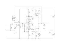
This is the sort of circuit which might be useful. It uses a JFET input opamp to avoid bipolar bias currents; I think that this one (the single version is OPA604) might be obsolete but that there are replacements which should also work. The transistor output stage provides the grunt. I am sorry I have not had time to build and test this, but simulations show it's OK, though I would add an RC load (47nF-10 ohms) to the output to provide a load at high frequencies if the output is disconnected.
I am sure the folks on this site may have some comments, but options are possible such as running the op amp from 15V rails and the output from higher voltages.
The quiescent current stability is my biggest concern: being symmetrical, two stabilisers are used, one for upper output and one for the lower. The four transistors need to be mounted together for each half, but because of the independent heatsinks (you can use one though) the bias should be stable even running with a D.C. output voltage. I have used 1 ohm emitter resistors rather than the usual lower values as a precaution.
I've called this DCAmp with an X for experimental (until proven).
Attachments
Oops - error in diagram. Capacitors across bias stabilisers should be connected to ground not op amp output.
- Status
- Not open for further replies.