😕 I've been trying to learn to design audio power amplifiers for years now and can't find the righ information...
I know a lot of the theory and ohm's law. Only problem is, I can't figure out how to pick a level of gain for a transistor or a Q point operating current or voltage. For example, I would like to build a
simple 100 watt into 4 ohm class a amplifier... I wanted to use
2n3055's for the output but the only charts I can find say
x amount of gain at a collector to emitter voltage of 4, whereas
I need a collector emitter voltage of like, 30 per transistor in the O/T stage and I don't know how much gain they'll have at that voltage.. Can somebody please help me?😕
The transistor's Hfe is not really the deciding factor in your amplifier's voltage gain. Using this circuit (which is a great DIY circuit for anyone from beginners to EE's) as an example, the ratio of R4 and R5 determines the voltage gain. R5 must = R2. R2 determines the input impedance of the amp. Q9 controls Vbias, and so Iq is controlled by VR1. Q9 is mounted on the heatsink to automatically adjust Vbias as temperature changes so the OPS won't go into thermal runaway. This is basically the same for almost all amps, but MOSFET amps don't require thermal tracking.
Also, 2N3055/MJ2955 transistors are not what we call ideal for big power amps, especially class A. They have high internal thermal resistance, small SOA, low Vceo (output devices must withstand the sum of the rail voltages), and are not well matched, just to name a few problems. I suggest MJ15003/MJ15004 devices they are a little more expensive, but sooooo much better. 2SA1302/2SC3281 devices are also better, and much easier to mount because the're in flatpack cases (TO-247) but the're hard for the average DIYer to find. There are substitutes though.
If you want to go class A, maybe you should try MOSFETS, like the 2SJ162/2SK1058 or IRFP240/IRFP9240.
You have lots of choices, good luck!
Attachments
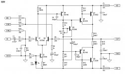
Q9 must NOT be mounted on the main heatsink. The output stage of this amp is a CFP and its quiescent current is determined by the driver transistors Q5 and Q6. Temperature compensation of Vbias is therefore achieved by thermally connecting Q9 with either Q5 or Q6.
😱 Ahh! Sorry about that! I never even looked at the OPS config. He's right. With CF (complementary feedback, the collectors of the OPS go to output), Q9 follows the drivers, with EF (emitter follower, the emitters go to out), it follows the OPS. Also, with EF, the drivers' emitters go to the OPS's bases. My bad.
Actually, like I said in another thread, I do have a bunch of 2SA1492 and 2SC3856 which are the same as 2SA1302 and 2SC3281 as far as I know.
- Status
- Not open for further replies.