If the negative driver arrangement does affect PSRR, you might put some LEDs or a zener in series with R12 so it can be reduced to 10k so that the variation with rail voltage will cancel.
Yes, that's a good idea. I was thinking to run both R1 and R12 from a filtered voltage, although wrt the negative rail, not ground, which may cause an issue if there is a lot of supply ripple. Some amps resort to extra supply voltages, but I don't much like that option. Are we just covid bored?
The idea of a NPN only circuit is a novelty and not a means to the best performance.
Oh no: we're far beyond that point already. At least you can match transistors!
If only I could spare more time...
NPNCCCM
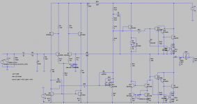
The capacitor between R14 and ground got lost somehow.
The output is a two-stage emitter follower. This had caused a lot of issues with the current mirror/resistor, and only after changing to three-stage EF those issues were gone. I can't see any reason why two-stage should work with the new circuit so that would be better a three-stage EF.
Apart from that, the whole mechanism is different. The "npncccm" design is only activating the current mirror during the negative half wave. This does some visible distortion at 20kHz. In contrast, the current mirror is perfecly linear - see below.
CURRENT MIRROR
Some circuit analysis:
V_R25 = V_out +V_Rail -2x.65 -V_be_out (note: V_be_out includes the voltage along the emitter resistor)
V_R10 = V_Rail -.65 -V_mult +.65 -.65 +V_be_out +.65 +V_out
and with R10=R25, and i_R10=i_R25, we have V_R25=V_R10
--> V_mult = 2x.65 + 2xV_be_out (I have used ~3V)
V_Rail cancels and this equation is valid for any V_out. This makes it such a nice architecture.
So I'm a fan of the current mirror but not of the NPNCCCM.
Here are the results for the temperature dependency of the Vbe multiplier. For the tests I have manually adjusted the Vbe multiplier to reach 50mA, after reaching various temperatures.
25°C 2,75V
40°C 3,2V
60°C 3,3V
While on most topologies the voltage needs to drop at increasing temperatures, here the voltage needs to increase. With constant Vbe multiplier at increasing temperature the idle current would drop.
Also the dependency is strong so NTC-based compensation is not a good idea. And I see a strong hysteresis when I compare heating up to cooling down, although using a quite big heatsink.
--> Based on above equation for V_mult it should be the opposite (the normal case). Where is the mistake? Maybe the source is not the output transistor temperature (how could a calculation be wrong) but something else?
The problem with the current mirror and resistors as a diff-amp is that inaccuracies in the current mirror translate to a significant offset, which means unpredictable idle current in this situation.
How? The Vbe multiplier is adjusted with the trimpot based on measurements. Transistors are perfectly matching (BC847BS).
I would like -or I need- to better understand the source of the thermal drift.
Question,
What is your goal?
I mean, why do all this?
Fundamental research or the quest for sound?
What is your goal?
I mean, why do all this?
Fundamental research or the quest for sound?
The Altec 9440A schematic that I found on-line is a huge quasi, with lots of PNP transistors for drivers, VAS, etc.Doesn't the Altec 9440A fit the bill?
So concerning the thermal drift I now understand the high dependency on the current mirror. We have 2mV/°C on Vbe and this translates to a current offset of 4uA (at 2mA steady state and 100 Ohm degeneration resistor). Over the resistor R25 that makes 100mV which is a big value as it drives the triple emitter follower, leading to 60mA drift. 1°C does 60mA then? So you have been correct, that's the source.
I have compared both options of 1) a 4-transistor-mirror, and 2) a normal mirror with higher degeneration resistor plus a diode to balance voltage drop. The normal current is 2mA.
1) The 4T mirror perfectly balances the voltage especially during high signal magnitudes. However the degeneration resistor is maximum 330 Ohm to safely turn off the emitter followers.
2) The normal current mirror, even if balanced in steady state with an additional diode, has quite different voltage drops on both mirror transistors during high signal magnitude. So when the Amp is working the load on both transistors is different. However the degeneration resistor can be easily 100 Ohm more.
Finally the issues appeared during load. Therefore the 4T mirror, together with a <330 Ohm degeneration resistor, should solve this problem.
Concerning the bad operation of the current limiter, I believe the returning current of D9 (discharge base of top transistor) was the problem. This diode is always active if the lower current limit is active. I don't believe that diode is required so removing it is a solution. Then, also no overcurrent protection on the VAS is needed anymore.
Oh and I had the wrong .asc file in my post. Nobody noticed 🙂
Finally I compared the VAS with CCS and with bootstrap and the bootstrap reaches a higher max voltage (Range with bootstrap is -18.33 to 18.33 compared to the CCS range-18.44 to 17.7, at supply +-22V). I'll go for the bootstrap. It's a pity for the nice CCS circuit.
21 npn transistors, 0 pnp transistors.
Suggestions welcomed while the next build may have to wait a considerable time.
If only I would know.why do all this?
Attachments
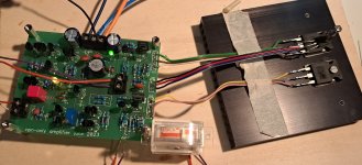
Welcome back to the topic after a little break.
Changes:
During powerup the current was -Imax and then +Imax for about 1 second, not very healthy for a speaker. I added a constant current source on the input stage on the tail of the differential, startup is now ok.
The thermal compensation is very fine. Q6 (BD139) is directly screwed on the output transistor Q8. I expected undercompensation (as the Vbe multiplier is set to 1.6 and not 2) but it's working very fine (various setpoints / temperatures all stable).
Funny thing how the current mirror is, if you touch Q17 with a finger you can see the current dropping. But quiescent current stays constant under different temperatures and load. I didn't even need to glue the transistors together, there is no drift.
Main problem was a 250kHz oscillation with approx 2mV modulating the output.
I added base stoppers for the predriver (68 ohm) and driver (22 ohm) but I think they're not required.
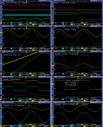
Results are attached.
There is a slight issue when clipping at the positive rail under very high frequencies. It doesn't appear at normal frequencies and only at clipping. The diodes don't affect this (removed them, no change) and the 47pF caps also don't affect it in any way. Maybe the transistor choice is too simple (now it's BC556b from eBay, BD139 and TIP35C).
Peak output is +-15V at a 22V (15VAC rectified) supply. For sure the expectable downside of this circuit but no issue.
A class-AB amp using only npn transistors.
Changes:
During powerup the current was -Imax and then +Imax for about 1 second, not very healthy for a speaker. I added a constant current source on the input stage on the tail of the differential, startup is now ok.
The thermal compensation is very fine. Q6 (BD139) is directly screwed on the output transistor Q8. I expected undercompensation (as the Vbe multiplier is set to 1.6 and not 2) but it's working very fine (various setpoints / temperatures all stable).
Funny thing how the current mirror is, if you touch Q17 with a finger you can see the current dropping. But quiescent current stays constant under different temperatures and load. I didn't even need to glue the transistors together, there is no drift.
Main problem was a 250kHz oscillation with approx 2mV modulating the output.
- It was not there in earlier circuits so it might be due to the 4T mirror. Everything was checked and changed without effect: very high miller cap, VAS, bootstrap replaced by CCS, Zobel network, different output transistors with fT = 2.5, 3, and 30MHz, improved grounding, base stoppers on current mirror, lower emitter resistors.
- Finally I added a 47pF between VAS output and the inverting input (found it in https://www.diyaudio.com/community/threads/base-stoppers.70309/). I learned it's "input-inclusive semilocal feedback" (Book from D. Self), or the JLH miller cap. Wow. Any value between 22pF and 100pF solves the problem. It's very stable now and I can remove the weird RC in parallel to the normal miller cap. However I must keep the regular miller cap. So I put 47 pF as normal miller cap (between VAS output and VAS input) AND 47 pF as JLH miller cap (between VAS output and inverting input).
- Question: for the JLH miller cap, the values of the feedback resistors is very important. If they are too big then transients are really slow (The old designs with this feedback seem all to use big resistors). It also corrupts the feedback value as it draws current from the voltage divider. However if they are too small then you have R5 being too small and the cap C1 needs to be big. I determined 250 Ohm / 5 kOhm as tradeoff. Any documentation on designing this?
I added base stoppers for the predriver (68 ohm) and driver (22 ohm) but I think they're not required.
Results are attached.
There is a slight issue when clipping at the positive rail under very high frequencies. It doesn't appear at normal frequencies and only at clipping. The diodes don't affect this (removed them, no change) and the 47pF caps also don't affect it in any way. Maybe the transistor choice is too simple (now it's BC556b from eBay, BD139 and TIP35C).
Peak output is +-15V at a 22V (15VAC rectified) supply. For sure the expectable downside of this circuit but no issue.
A class-AB amp using only npn transistors.
Attachments
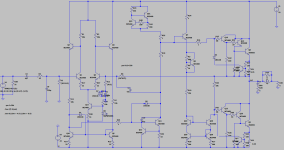
You can improve the output voltage range by:
1. Adding a bootstrap above the VAS CCS to improve the positive swing.
2. Adding a balanced pre-bias to the current mirror to move its common mode range down to the negative rail.
I have to admire your persistence. I find this interesting but unlikely I'd actually spend the time etc on it. BTW, I have found that a class AB variation on the JLH circuit can work reasonably well, ie no current mirror, and the diode idea can work well, aka op-amps 5532 and LM833 etc.
- Home
- Amplifiers
- Solid State
- Amplifier with only 1 type of transistors