Hello.
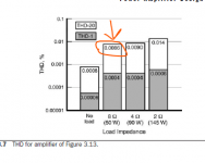
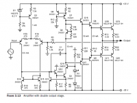
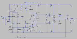
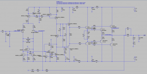
On page 68 of the book "A u d i o P o w e r A m p l i f i e r B a s i c s" by Bob Cordell there is a diagram
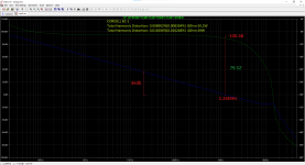
"Figure 3.13 Amplifier with double output stage". I tried to model it in lt-spice. That's how I described it (picked it up) and that's what I got. I got an order of magnitude more distortion. Did I do something wrong?
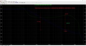
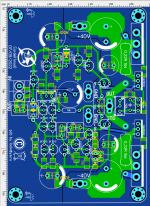
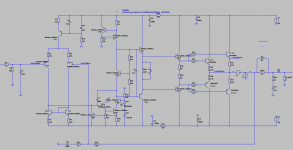
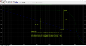
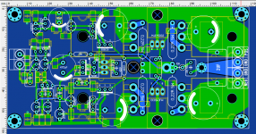
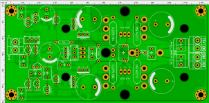
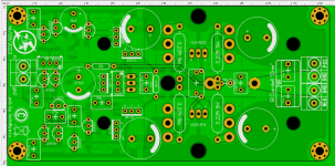
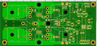
That was the first question. The second one will be next. So I made such improvements and got such a result. What do you think, colleagues, will this work in hardware in reality? I even made a psb for research in a hurry. Is there something that I didn't take into account, which is why my version of the amplifier may not work (I'm talking about both options, but of course I'm more interested in the second option).
On page 68 of the book "A u d i o P o w e r A m p l i f i e r B a s i c s" by Bob Cordell there is a diagram
"Figure 3.13 Amplifier with double output stage". I tried to model it in lt-spice. That's how I described it (picked it up) and that's what I got. I got an order of magnitude more distortion. Did I do something wrong?
That was the first question. The second one will be next. So I made such improvements and got such a result. What do you think, colleagues, will this work in hardware in reality? I even made a psb for research in a hurry. Is there something that I didn't take into account, which is why my version of the amplifier may not work (I'm talking about both options, but of course I'm more interested in the second option).
Attachments


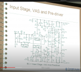
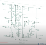
I can say that we simulated, built and tested the BC-1 amplifier, as described chapter 4 of the 2nd edition. It performs very well.
Basically the same as what you posted except no VAS cascode.
Basically the same as what you posted except no VAS cascode.
And where can I see the final scheme of this BC-1 and read about it? Is there a topic for discussion?
I started a thread on the subject in this section, try doing a search for “BC-1”. I’d post the link if I could figure out how to do it on this phone I am using to respond to you 🙂
Good to see you found that YouTube presentation. Look for the thread showing the completed design

There were 2 questions.:
1. The purpose of VT10 (do I understand correctly that this is a kind of tracking that is implemented directly in the current mirror?
2. Which of the transistors: VT18 or VT14 should be attached to a common radiator?
1. The purpose of VT10 (do I understand correctly that this is a kind of tracking that is implemented directly in the current mirror?
2. Which of the transistors: VT18 or VT14 should be attached to a common radiator?
This is described in the 2nd edition of the book, chapter 4, which I am assuming that you do not have or can not obtain, so to be fair, I will provide you with this information.
1. The current mirror (VT1, VT16) includes an emitter follower “helper” transistor, VT10 that supplies the base current for the mirror transistors. This improves mirror accuracy and causes the collectors of both IPS transistors to be at the same DC potential as a result of the 2Vbe input voltage of the 2T VAS. Emitter degeneration voltage drops in the current mirror and VAS are made the same.
2. VT18 is mounted onto one of the OPS devices. VT1 is mounted on a heat-spreader along with the pre-drivers VT15,17

I have a design of a similar amp to that one on a github
http://www.github.com/profdc9/PowerAmpAudio
It adds some additional features such as output current limiting. I also did not use the VAS cascode as under simulation it didn't seem to make any improvement. I also "flipped" the supplies to allow the LTP to be low-voltage, low-noise transistors using a cascode on the input. I elected to use a double rather than than a triple stage darlington in some cases for better stability. The THD can be low enough (< 0.01%) with a double stage in many cases without having to deal with stability issues.
Also, sometimes THD can be because there is too little VAS current, or the VAS current protection (Q13/R6) kicks in at too low of a current. Too low of a VAS current can cause slew rate limiting which shows up as distortion at higher frequencies.
- Home
- Amplifiers
- Solid State
- Amplifier with double output stage by Bob Cordell