What can I technically do when designing an amplifier to make it add plenty of second harmonic?
Create distortion is not too difficult.
But to generate mostly 'earfriendly' second harmonic - how do we do this?
I have one suggestion.
It is wellknown that big MOSFETs generate some 2nd.
But more specifically how do we add them?
How do we build?
Give from your experience and tell me.
Thank you.
Create distortion is not too difficult.
But to generate mostly 'earfriendly' second harmonic - how do we do this?
I have one suggestion.
It is wellknown that big MOSFETs generate some 2nd.
But more specifically how do we add them?
How do we build?
Give from your experience and tell me.
Thank you.

Single-ended Class B will give you lots of 2nd.
For a controllable amount, combine a 'clean' channel with a precision full-wave rectifier channel (standard op-amp plus diodes circuit). Use a pot to mix in as little or as much distortion as you like.
For a controllable amount, combine a 'clean' channel with a precision full-wave rectifier channel (standard op-amp plus diodes circuit). Use a pot to mix in as little or as much distortion as you like.
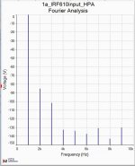
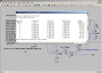
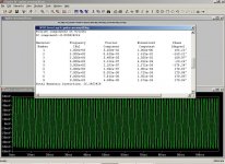
Here is something what mean.
It is a small headphone amplifier
with IRF610 diff pair input
and a single end IRFP240 output fed from current source.
There are no bipolar doing any gain.
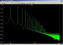
This harmonics spectra speak for itself.
You get the third harmonic along with the second.
It is a small headphone amplifier
with IRF610 diff pair input
and a single end IRFP240 output fed from current source.
There are no bipolar doing any gain.
This harmonics spectra speak for itself.
You get the third harmonic along with the second.
Attachments
Use an input differential with a poor current source , typicaly a resistor
connected to a zener voltage reference.
Very interesting. Will give that a go!
What can I technically do when designing an amplifier to make it add plenty of second harmonic?
Give from your experience and tell me.
Thank you.
Forget altering the amplifier and get hold of a soft limiter which will give a more rounded wave with plenty of even harmonics.
Single-ended Class B will give you lots of 2nd.
I think you want single-ended Class A. Class B implies that the output device shuts off for half of the cycle, which would create massive distortion of all kinds.
Regards,
Rob
My suggestion of single-ended Class B was slightly tongue-in-cheek, as was (I assume) the Class C suggestion from jcx. However, SE Class B still produces mainly fundamental and 2nd.
Single-ended Class A can give very little distortion.
Single-ended Class A can give very little distortion.
Hi lineup,
In this book there is a simple circuit with two jfets wich generates your second harmonic. I don't remember the page. Maybe someone here in this forum have it. I have one but unfortunately it is so far way from me at this moment.
Field-effect transistors (Texas Instruments electronics series): Leonce J Sevin: Amazon.com: Books
Regards
eD
Member
Joined 2009
Paid Member
You can do it easily with almost any feedback push-pull amplifier like this:
http://www.diyaudio.com/forums/solid-state/168503-tgm-amp-goes-tubey.html
I've looked at other options before too:
http://www.diyaudio.com/forums/solid-state/186817-biguns-bootstrap.html
And Hugh Dean of AKSA fame is probably the best at tuning amps for a good harmonic profile, usually favouring H2.
Danielwritesback talks about putting a diode in parallel with a resistor in the +ve supply rail for the same result, here (post 62):
http://www.diyaudio.com/forums/chip-amps/129692-chip-amp-you-like-most-4.html#post3219561
Last edited:
Perhaps a highly asymmetrical output stage - quasi maybe? Also a singleton input stage and single ended vas.
This configuration is the basis of the design I am currently working on and it is looking very promising!
This configuration is the basis of the design I am currently working on and it is looking very promising!
Another radical solution...
An externally hosted image should be here but it was not working when we last tested it.
Don't be too focused on just H2 distortion. The most desired distortion is said to be low order; i.e. H2,H3,H4,H5 in declining magnitude.
AFAIK, that's like Jerluwoo's graph in post #7 or your #5. It's probably easier to generate that desirable type of distortion "profile"
than any single harmonic.
AFAIK, that's like Jerluwoo's graph in post #7 or your #5. It's probably easier to generate that desirable type of distortion "profile"
than any single harmonic.
Last edited:
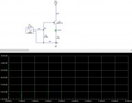
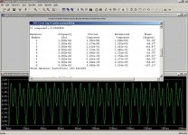
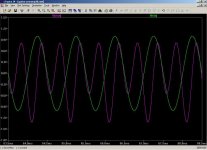
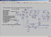
Originally designed as a guitar distortion preamp I added R17 so the input is +-1V instead of +-10mV. Just mix Vout and Vin to get as much distortion as you want.
Schematic, FFT 1Khz, Vin-Vout 1Khz, distortion 1Khz, distortion 100hz
Schematic, FFT 1Khz, Vin-Vout 1Khz, distortion 1Khz, distortion 100hz
Attachments
Last edited:

- Home
- Amplifiers
- Solid State
- Amplifier with a sound. How to build for second harmonic.