If you haven't yet found this thread - it's a good start to get you measuring from a few Hz to 96kHz, with automatic gain and phase response plotting, as well as a scope and all sorts of distortion testing, and provides a signal oscillator that I got down to 0.0006% THD.
Howto - Distortion Measurements with REW
There are soundcards that will now sample to 384kHz and extend the measurement response to 192kHz.
Howto - Distortion Measurements with REW
There are soundcards that will now sample to 384kHz and extend the measurement response to 192kHz.
The thread starter started with "So you've built a diy amp,.....",and reading all the responses my opinion is
that if it is not your goal to get your design into production either mass or restricted, and just have made the design for your own use,
why not the practical approach: Some fiddling around with capacitors/resistors across the feedback network and modifying it a little,
driving the amp with small and large input signals (sinewave and/or square wave), and monitoring the output signal for instability.
When there are no more signs of instability (take a dummy load which is almost similar to the used speaker load), then leave it that way.
In the long, long past when I was designing transistor class b amplifiers which were for production purposes, then quite a different
approach was necessary of course.
Now, when I am building tube headphone amplifiers as a hobby and apply some NFB, I execute this practical approach.
If you haven't yet found this thread - it's a good start to get you measuring from a few Hz to 96kHz, with automatic gain and phase response plotting, as well as a scope and all sorts of distortion testing, and provides a signal oscillator that I got down to 0.0006% THD.
Howto - Distortion Measurements with REW
There are soundcards that will now sample to 384kHz and extend the measurement response to 192kHz.
Thats really useful to know I have a TASCAM 16x08 USB ADC/DAC.
The instability on a real load is a property of NFB amplifiers using a pentode OP section. If the amp has been setup on a test resistance to be the 20 db that most build for, there will be a lot more that 20 db at any of the resonances of a real load. 20 db can easily become 30-40 db & instability is a sure thing. A penode is a current device so the voltage at the load simply follows the impedance curve of the load. The full loop NFB does not control the gain of the output tubes, it controls the stage it is attached to.
OTOH, the gain of a triode OP section in limited by the mu of the tube such that gain increases only about 2 db at the load resonances. Do the Math!😀
OTOH, the gain of a triode OP section in limited by the mu of the tube such that gain increases only about 2 db at the load resonances. Do the Math!😀
jhstewart, it is typically the resonances occurring outside the normal mid-range +20dB loopgain band, when forward gain of the amp has dropped by 20dB or more, and where output transformer related resonances are the cause of instability with peaking responses that can often be greater than 2dB with triode output stages. Even the venerable Williamson amp showed +6dB.
The load resonances are mostly in the audio band, they are a result of the loudspeaker itself. But any problem that might be in the load outside the OPT band limits could cause even more problems.
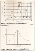
Unported speakers usually have one resonance, typically 50-200 Hz, depends on size, magnetic circuit, cone mass & so on. Bass reflex have two resonances in the same freq range, some self damped better than others. The impedance of most speakers rises from some mid-audio band freq out to 20 KHz & beyond. The addition of a X-over network & mid & High freq loudspeakers complicates all.🙂
Unported speakers usually have one resonance, typically 50-200 Hz, depends on size, magnetic circuit, cone mass & so on. Bass reflex have two resonances in the same freq range, some self damped better than others. The impedance of most speakers rises from some mid-audio band freq out to 20 KHz & beyond. The addition of a X-over network & mid & High freq loudspeakers complicates all.🙂
I don't think any mid-band resonances will cause an instability issue, and only cause level variations, similar to tone control, speaker, or room level variations. Certainly, if the level varied close to the zero crossing loop gain frequency region, and modified the gain or phase margin, then a stability issue may arise.
Pentode approximate gain is usually taken as Gm*Rl. However a more accurate approximation is Gm*Zl, that takes into consideration of a complex load such as a loudspeaker. So if the loudspeaker impedance increases 3-4 times at resonance, the pentode stage gain will increase by a like amount.
NFB taken to the front end of the amplifier will reduce the gain of the stage it is applied to. The gain of the output stage doesn't change at all, it will still be high.
The NFB required to get the amplifier back to normal increases by whatever the pentode stage gain increase is.
So NFB that may have been set to 20 db now is perhaps 30-40 db. The problem is in the amplifier whether a signal is at one of those resonent frequencies or not.🙂
Triode output stages are affected far less. Their gain can only increase by an amount limited by mu.
Attachments
That's fine, but it may not cause unstable oscillation, or gross ringing, unless there is interaction with the loop-gain zero crossover region. For example, zero cross over could be 3Hz, and mid-band gain could be -3dB at 30Hz. For sure, if an amp has a high zero crossing at 30Hz, then that may cause instability.
NFB will only fully restore mid-band frequencies, as the level of NFB drops outside that band due to the forward gain dropping (from CR coupling time-constants and output transformer inductance).
NFB will only fully restore mid-band frequencies, as the level of NFB drops outside that band due to the forward gain dropping (from CR coupling time-constants and output transformer inductance).
Hi guys
I have a question
Audio signals have Spectrum from 20 Hz to 20 kHz.
Let's suppose there is a peak in the frequency response of an amplifier at 50 kHz.
There is no audio signal at this frequency.
How this resonance could be excited (amplifier loaded with a speaker) ?
I have a question
Audio signals have Spectrum from 20 Hz to 20 kHz.
Let's suppose there is a peak in the frequency response of an amplifier at 50 kHz.
There is no audio signal at this frequency.
How this resonance could be excited (amplifier loaded with a speaker) ?
As I understand it in a closed loop like an amp with NFB applied at some point the phase difference between the IP and OP gets bigger, until the signal being fed back is positive.
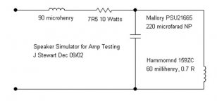
In Radio Designers he says some components in an amp, for instance the cathode bypass cap can be degenerative or regenerative, meaning one will stop any spurious oscillation and the other will encourage oscillation. Things like speakers also have a resonant peak, get any speaker, feed it with a signal sweep and monitor the voltage across the terminals, at some frequency you'll get a big peak, this is true with speaker cabs too.
All this means I think, is that a certain combination of components will encourage the amp to start singing, so, by testing with a capacitor as the load for instance were trying to find out where the amp is likely to oscillate.
Hope that helps, my grasp of the subject is sketchy, any attempt to read up on the subject and my brain switches off, the language used in a lot of sources on the subject is dense and opaque, the authors often assuming your a post grad maths scholar and or nuclear physicist, making it hard for beginners like myself who left school 30 years ago with sod all bits of paper struggle with the subject. Still, I keep plugging away, the penny will drop one day.
Andy.
Crowhurst is one of the easier authors to read as he provided lots of diagrams and photos in his articles and books - a picture is worth a thousand words to many of us - and his articles and books were targeted at the hi-fi/electronics enthusiast, rather than to be presented at a technical conference.
Just a few imho pertinent links, with many more around.
https://worldradiohistory.com/BOOKSHELF-ARH/Technology/Audio-Measurements-Crawford-Gernsback-1958.pdf
https://www.dalmura.com.au/static/crowhurst%20stabilizing%20feedback%20amps.pdf
1956 High Fidelty Circuit Design book Manuals - KO4BB
Just a few imho pertinent links, with many more around.
https://worldradiohistory.com/BOOKSHELF-ARH/Technology/Audio-Measurements-Crawford-Gernsback-1958.pdf
https://www.dalmura.com.au/static/crowhurst%20stabilizing%20feedback%20amps.pdf
1956 High Fidelty Circuit Design book Manuals - KO4BB
Last edited:
Thanks again trobbins, your Norman's books are easier to read, forgot about him. I'll have a look into those links, cheers, A.
Thanks throbbins for giving those links!
Particularly this link:
https://www.dalmura.com.au/static/cr...ack%20amps.pdf
and turning to page 35 page, the diagrams in Fig.4 show all about the stability subject :
Gain- and Phase margin of a particular design.
Particularly this link:
https://www.dalmura.com.au/static/cr...ack%20amps.pdf
and turning to page 35 page, the diagrams in Fig.4 show all about the stability subject :
Gain- and Phase margin of a particular design.
JoeAlders, I hate nyquist diagrams, and smith charts for that matter, as they take too much effort to appreciate - but I guess if you look at them all day long then things would be different.
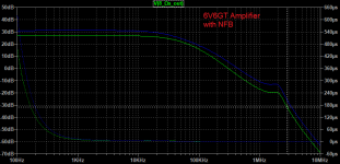
I can appreciate that back in Crowhurst's day just having to draw/draught up one diagram was easier than two, but a modern day advantage is that software programs can happily do a spectrum response sweep in seconds and overlay the gain and phase plots, and allow that to be captured and sent around the world or seen by a forum in a few seconds - we are very lucky indeed.
Another interesting aspect of that Crowhurst article is that he purposefully sidesteps getting in to a particular amp's feedback design, and a rabbit hole of possible circuit design equations and assessments, and rather just recommends having a quick jiggle of likely part changes, and then follow your nose as to the most sensitive influence. Although a good practical start to working through an issue, there is a lot to recommend about crunching some numbers as to what corner frequencies are in play, and appreciating what one is actually doing when jiggling part values. I tried to do that with the basic Williamson amplifier, as there wasn't much around that went in to heavy detail - it was an enlightening process.
Last edited:
I just wanted to say...
...what a helpful thread this is!
I have been attempting to stability test a small amplifier I have been testing (a small 6V6/6P6S SET) and reading this thread, and the "too much local feedback" thread, has left me feeling, that I may be on similar ground regarding
perhaps achieving only conditional stability, FB local and global, OPT resonances all having their impact on stability/transient behaviour.
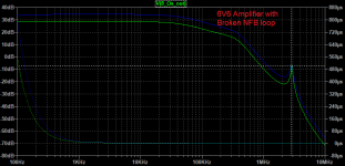
(I have had an issue with multiple OPT resonances, out of band, which were constrained nicely in the absence of gNFB by limiting feedback bandwidth simply, with a capacitance (or RC) in parallel to the feedback resistor - but when global FB was added the resonances resulted in excessive gain peaking, with more power delivered to the load above the range of audibility. Mitigation measures treated the symptom and not the cause, I.e. secondary winding RC and feedback RC network, lessened the problem; but the secondary winding RC just burned up the extra power - the valves still felt the strain.)
It's been a learning experience, for sure, and this thread has helped a lot!
I will be interested in the phase method described, using scope XY plot and Lissagious figures
...what a helpful thread this is!
I have been attempting to stability test a small amplifier I have been testing (a small 6V6/6P6S SET) and reading this thread, and the "too much local feedback" thread, has left me feeling, that I may be on similar ground regarding
perhaps achieving only conditional stability, FB local and global, OPT resonances all having their impact on stability/transient behaviour.
(I have had an issue with multiple OPT resonances, out of band, which were constrained nicely in the absence of gNFB by limiting feedback bandwidth simply, with a capacitance (or RC) in parallel to the feedback resistor - but when global FB was added the resonances resulted in excessive gain peaking, with more power delivered to the load above the range of audibility. Mitigation measures treated the symptom and not the cause, I.e. secondary winding RC and feedback RC network, lessened the problem; but the secondary winding RC just burned up the extra power - the valves still felt the strain.)
It's been a learning experience, for sure, and this thread has helped a lot!
I will be interested in the phase method described, using scope XY plot and Lissagious figures
I can appreciate that back in Crowhurst's day just having to draw/draught up one diagram was easier than two, but a modern day advantage is that software programs can happily do a spectrum response sweep in seconds and overlay the gain and phase plots, and allow that to be captured and sent around the world or seen by a forum in a few seconds - we are very lucky indeed.
In the chapter on amplifier testing, Crowhurst suggests measuring the amplifier output impedance with respect to frequency to gauge stability. I use this method (called non-invasive stability measurement) for measuring voltage regulator stability.
You can plot Z with respect to frequency and measure "Q" (or if you have a fancy network analyzer, calculate "Q" from group delay). Without getting into the math, if Q is 1.1 or less, phase margin is 45 degrees or greater.
Speaking of draftsmanship -- Paul Dirac ("The World's Strangest Man"), discoverer of anti-matter and Nobel Laureate credited some of his success with his early study of drafting in high school.
- Home
- Amplifiers
- Tubes / Valves
- Amplifier stabilty testing methods.