I am planning to build/rebuild a protection board I built earlier that was based on the Apex schematic provided by user @apexaudio in other threads.
The idea is to take the original output relay which is a mechanical relay and replace it with solid state switches, a pair of Mosfets forming a bidirectional electronically controllable switch.
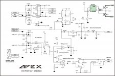
Recently there is a new type of optocoupler that uses RF signalling to transfer energy internally. There are two types of this IC one is Si8751 which is logic controllable and Si8752 which is analog type. I am planning to use the Si8752 I have attached the modified schematic showing the modified circuit.
Since the original circuit uses a negative -24v supply for the relay coil, I simply rearranged that supply so that it would fit the Si8752 input diode.
Since this is a stereo circuit originally made for two channels I think I will put two Si8752 inputs in series with the -24v supply.
Maximum input current for the Si8752 is 30mA per datasheet. Voltage drop is around 2.5 volts close to the rated 30mA.
What do you think , any ideas, suggestions?
I have also found that the 7912 voltage regulator in the FAN output is not necessary if one wants the fan to just start working over set temperature and not working before that.
The Dc protection input resistors can be changed from 150k to lower value to allow for trigger at lower DC voltage. While doing tests I found that if changing just the input resistor , around 100k triggers the DC at 12v, and around 60k allows for 6v DC trigger.
Maybe the 22uF capacitor value is too large and needs to be smaller.
Haven't tested it with sine wave with amplifier yet but please refer to the discussion here
https://www.diyaudio.com/community/threads/900w-h-class-pa-amp-with-limiter.162408/page-164
The idea is to take the original output relay which is a mechanical relay and replace it with solid state switches, a pair of Mosfets forming a bidirectional electronically controllable switch.
Recently there is a new type of optocoupler that uses RF signalling to transfer energy internally. There are two types of this IC one is Si8751 which is logic controllable and Si8752 which is analog type. I am planning to use the Si8752 I have attached the modified schematic showing the modified circuit.
Since the original circuit uses a negative -24v supply for the relay coil, I simply rearranged that supply so that it would fit the Si8752 input diode.
Since this is a stereo circuit originally made for two channels I think I will put two Si8752 inputs in series with the -24v supply.
Maximum input current for the Si8752 is 30mA per datasheet. Voltage drop is around 2.5 volts close to the rated 30mA.
What do you think , any ideas, suggestions?
I have also found that the 7912 voltage regulator in the FAN output is not necessary if one wants the fan to just start working over set temperature and not working before that.
The Dc protection input resistors can be changed from 150k to lower value to allow for trigger at lower DC voltage. While doing tests I found that if changing just the input resistor , around 100k triggers the DC at 12v, and around 60k allows for 6v DC trigger.
Maybe the 22uF capacitor value is too large and needs to be smaller.
Haven't tested it with sine wave with amplifier yet but please refer to the discussion here
https://www.diyaudio.com/community/threads/900w-h-class-pa-amp-with-limiter.162408/page-164
Attachments
Been dicking with Audio since 1966 Was even diying a TT in '69 . Soo A looong time.
I've Never had 'speaker protection' And also Never had a speaker get eaten by an Amp.
A solution to a nonexistent problem ....it seems to me.
I've Never had 'speaker protection' And also Never had a speaker get eaten by an Amp.
A solution to a nonexistent problem ....it seems to me.
The problem is very real if you’ve been building big enough amplifiers or beating on them hard enough. Even if they don’t outright fail you can get DC or ultra low frequency thru speakers - with dropped mics and feedback thru turntables. I’ve had speaker relays trip more often for that sort of thing than actual amplifier problems.
You could put 8 of those optos in series off a 24 volt supply. Multiple channels, or several outputs in series/parallel driving the FETs for faster switching.
I like the idea of a 2 speed fan - most of the time it will be relatively quiet. When it really gets hot it needs to go high speed. Two comparators and you could have two speeds plus off. A protection circuit I’ve been working on has multiple temperature trip points - the first engages the fan, next it speeds up, next it enforces clip limiting if it’s not already engaged, the next mutes the input and disconnects the speakers. All the trip points have a little hysteresis so it has to cool below the original trip point to back off on the protection level. And the final (at 100C) kills main power (in case of thermal runaway, where it continues the heat up with no load) and must be unplugged to reset.
According to my found this is a protection for Public Andres amplifiers.The problem is very real if you’ve been building big enough amplifiers or beating on them hard enough. Even if they don’t outright fail you can get DC or ultra low frequency thru speakers - with dropped mics and feedback thru turntables. I’ve had speaker relays trip more often for that sort of thing than actual amplifier problems.
You could put 8 of those optos in series off a 24 volt supply. Multiple channels, or several outputs in series/parallel driving the FETs for faster switching.
I like the idea of a 2 speed fan - most of the time it will be relatively quiet. When it really gets hot it needs to go high speed. Two comparators and you could have two speeds plus off. A protection circuit I’ve been working on has multiple temperature trip points - the first engages the fan, next it speeds up, next it enforces clip limiting if it’s not already engaged, the next mutes the input and disconnects the speakers. All the trip points have a little hysteresis so it has to cool below the original trip point to back off on the protection level. And the final (at 100C) kills main power (in case of thermal runaway, where it continues the heat up with no load) and must be unplugged to reset.
No need for small signal d.c detection.
Apex never answer in a complete about this.
If you want a home amplifier speaker protection circuit look for another solution.
Or wait for Apex answer.
Been dicking with Audio since 1966 Was even diying a TT in '69 . Soo A looong time.
I've Never had 'speaker protection' And also Never had a speaker get eaten by an Amp.
A solution to a nonexistent problem ....it seems to me.
Been dicking with Audio since 1966 Was even diying a TT in '69 . Soo A looong time.
I've Never had 'speaker protection' And also Never had a speaker get eaten by an Amp.
A solution to a nonexistent problem ....it seems to Some of us have had a different experience. Separately, I’d never ship an amp without protection. These things get hooked up to very expensive speakers. If you happen to blow the bass units on a $20 set of speakers what do you tell the customer?
I suppose if you ‘dick around’ with amps then you’ll never have seen the problem. A big amp powering up/down will be putting huge transients across the speaker - audibly unpleasant and not good electrically either. Secondly, what if you ship an expensive amp that gets hooked up to expensive speakers that, because the amp has no protection features, fries the speakers? When the customer comes knocking looking for compensation, what do you tell him?Been dicking with Audio since 1966 Was even diying a TT in '69 . Soo A looong time.
I've Never had 'speaker protection' And also Never had a speaker get eaten by an Amp.
A solution to a nonexistent problem ....it seems to me.
Seems to me eschewing amp/speaker protection is an extraordinarily irresponsible thing to do.
I added a varistor in the output which would shorten the speaker + to GND in case the MOSFET switch opens at a DC fault in the amplifier output because some speakers might have filter coils and coils tend to produce back EMF inductive spikes upon termination of current so in order for the MOSFET safe Uds not to be exceeded I thought some output shorting after the MOSFET'S have disconnected the amp would be good.
Now I think it should work like this, a DC fault is detected by the DC detect circuitry , the bidirectional MOSFET switch is opened ,at this moment the DC current in the output is terminated , upon this termination a backEMF spike can develop across the speaker + and GND terminals. In order for this spike not to exceed MOSFET safe operating area parameters and cause short circuiting of MOSFET's varistor or a TVS diode might be connected to the output which upon the voltage reaching a certain level would provide a path for the induced current to flow.
What do you think?
See the updated schematic please.
