
cool
great vork Gunderz
how does it sounds?
how about showing us the PCB? 🙂
do u have it?
i also want to ask which is the output power
Regards!
great vork Gunderz
how does it sounds?
how about showing us the PCB? 🙂
do u have it?
i also want to ask which is the output power
Regards!
well, there's no sound from the amplifier yet. We are not finished at this moment.
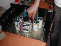
The amplifier does actually contain to amplifiers at the same PCB, it meant for bi-amping. One amp for bass and one amp for midrange and treble.
The power output is at leats 100W@8ohm, but could probably take more.
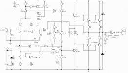
It's one of my friends who have made the PCB layout.
I can post the layout tomorrow.
The amplifier does actually contain to amplifiers at the same PCB, it meant for bi-amping. One amp for bass and one amp for midrange and treble.
The power output is at leats 100W@8ohm, but could probably take more.
It's one of my friends who have made the PCB layout.
I can post the layout tomorrow.
Hi Gunderz,
Looks good, but I think you should add some protection for Q7 and Q8. If you drive the amplifier hard into clipping Q8 will go into saturation and Q7 will blow because its Vce is quite high and suddenly also Ic will be high. You can solve this by incorporating a collector resistor for Q7.
Steven
Looks good, but I think you should add some protection for Q7 and Q8. If you drive the amplifier hard into clipping Q8 will go into saturation and Q7 will blow because its Vce is quite high and suddenly also Ic will be high. You can solve this by incorporating a collector resistor for Q7.
Steven
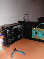
You might have some problems cooling the beast.
Those haetsinks dont look very large, and they are also mounted the wrong way (=no convection air movement).
Those haetsinks dont look very large, and they are also mounted the wrong way (=no convection air movement).
We are aware of the size of the heatsinks.
We have measured the thermal resistance to be 0,7 with the heatsink mounted the same way as the pictures show.
The chassis seen on the pictures are taken from an old amplifier.
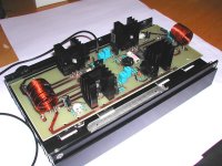
By the way.. at the front you could see a 4-order active linkwitz-riley filter.
We have measured the thermal resistance to be 0,7 with the heatsink mounted the same way as the pictures show.
The chassis seen on the pictures are taken from an old amplifier.
By the way.. at the front you could see a 4-order active linkwitz-riley filter.
looks very nice. 🙂
i would love to see some pcb layouts, including the linkwitz-riley filter, if you have it. 😀
i would love to see some pcb layouts, including the linkwitz-riley filter, if you have it. 😀
- Status
- Not open for further replies.
- Home
- Amplifiers
- Solid State
- Amplifier project(pics)