I am attempting to understand more about how to measure the output impedance of an unknown amp, say the circlotron I have built. I know about the formula involving mu and all that, but I'm intrested in a more direct approach, as the circlotron's unusual output topology, the formula might not be accurate....
I posted earlier with my idea of an AC ammeter in series with a variable load resistor, and was informed by a number of fellow bloggers that the correct approach is an AC voltmeter across a variable resistor...both ideas were tried and failed. With the ammeter in series mode, current simply went up as resistance went down, as expected, however when applying the output to an AC voltmeter across a variable resistor, the voltage simply went up, with no peak, till open circut, produced the highest. I'm using white noise, from an FM tuner as signal source. With a music input, results look good, I'm getting 10-12 watts of clean output into an 8 ohm speaker.
Early on, I was using a 2000 ohm 10 watt universal output transformer, but as I've gotten more of the bugs worked out, direct to speaker is now louder than with the transformer, which is a little suprising. Louder than that and the driver stages distorts. I'm in the process of re-designing the driver stage using the Grommes model 260A as a reference. I'm using four 6550's (borrowed from my mac), but I have space for six, so two more are on order. I plan on rewiring my old school, bose 901 speakers, in series to get 64 ohms impedance.
Could I be getting into trouble with such an arrangement with an uneven speaker impedance? Has anyone out there tried this arrangement of circlotron driving 64 ohm boses? I read that getting enough drive voltage to the output stage would be a problem, which I am finding even with non-triode outputs.
Last edited:
You measure the voltage across a resistor, call this V1 R1, then you measure the voltage across another smaller resistor (without changing the settings). Call this V2 R2. Then you calculate the output impedance:-
Z=(V1-V2)/((V2/R2)-(V1/R1))
Z=(V1-V2)/((V2/R2)-(V1/R1))
Last edited:
This was discussed, and, I thought, explained in the previous thread. The idea that I *think* you have in mind is that you want to adjust the variable load resistor until "something" is maximised. The problem is that what you would need to maximise is not the voltage across the resistor, nor is it the current flowing through the resistor. As you have now discovered, the unsurprising outcome if you try to maximise the current is that the resistance should be zero, whilst if you want to maximise the voltage the resistance should be infinity.
If you *really* want to try to measure the output impedance using this type of method, you must instead adjust the resistance so as to maximise the *power*. In other words, you would need to measure the current *and* the voltage, and then multiply them together to get the power. Then, adjust the resistor, remeasure the current and the voltage and multiply them together to get the new result for the power. If it is bigger than the previous value, then keep adjusting the resistor in the same direction, and try again. If it is smaller than the previous power, adjust the resistor in the opposite direction and try again. Keep on going like this, adjusting, remeasuring, recalculating, over and over again, until you home in on the resistance setting that maximises the power. A very clumsy and tedious process, and not at all to be recommended!!!!
Instead, the easy way to do it is as follows. Since in your case you are seemingly expecting an output impedance in the ballpark of 64 ohms, then do the following. Use a 64 ohm dummy resistive load in place of the speaker. Feed in a sinewave signal to the amplifier, and measure the AC output signal voltage on the 64 ohm resistive load. Then, leaving the inut signal unaltered, add an additional resistor in parallel with the 64 ohm load, and remeasure the output voltage across the load. With these measurements, you can calculate the output impedance, as follows:
To allow for more general cases, let's say the original resistive load you choose is R1 ohms. And that for the second measurement you connect an additional resistance R2 ohms in parallel with this. And suppose the output voltage you measure with the load R1 by itself is V1, and that the voltage after adding R2 in parallel is V2. The the output impedance is given by
Z = R1 * R2 * (V1 - V2)/(R1 * V2 - R2 * (V1-V2))
(I think I have the maths right. It is based on modelling the amplifier output as an ideal voltage source V0 in series with an impedance Z. It is then just a simple calculation of voltage dividers.)
In your case, as I said, taking R1= 64 ohms might be a good choice. For R2, I would suggest something of the order of 5 or 10 times R1, so, say, about 600 ohms. Of course, you will probably want to choose R1 and R2 to be actual resistance values you have or can easily obtain. The important thing is to know exactly what they are.
Much more typically, one would be measuring for an amplifier typically driving into an 8 ohm load, and so one would probably want to take R1 to be 8 ohms, and R2 maybe 47 ohms or so.
The results will not be perfect, but I doubt that you really need to know the output impedance very accurately in any case.
There is another method for measuring output impedance, involving the use of a second amplifier to driver a signal into the output of the amplifier under measurement. This is somewhat more involved to set up, even in the best of circumstances, and I don't think it is worth doing for your purposes. And in your case, it would be especially complicated to do it that way, because your amplifier is a circlotron, which means that neither of its output terminals is connected to ground. You would need to take special precautions to arrange to have a fully floating second amplifier to drive into the one you want to measure. It's just not worth it. The method with the R1 and R2 resistors I described above is the way to go, I think.
Chris
My reply #3 and couterculture's reply #2 came out more or less simultaneously. Our methods, and formulae are the same, but our notations are slightly different. His R2 is the same as my 1/(1/R1 + 1/R2).
Chris
Chris
re wire 901's
Hi there m: Based on replacement drivers for Bose 901's at Partsexpress being 1 ohm, so rewiring would not get you to 64 ohms. You could replace the 9 drivers with 8 ohm drivers to get close to your goal. ....regards, Michael
I am attempting to understand more about how to measure the output impedance of an unknown amp, say the circlotron I have built. ..... I plan on rewiring my old school, bose 901 speakers, in series to get 64 ohms impedance. Could I be getting into trouble with such an arrangement with an uneven speaker impedance? Has anyone out there tried this arrangement of circlotron driving 64 ohm boses? I read that getting enough drive voltage to the output stage would be a problem, which I am finding even with non-triode outputs.
Hi there m: Based on replacement drivers for Bose 901's at Partsexpress being 1 ohm, so rewiring would not get you to 64 ohms. You could replace the 9 drivers with 8 ohm drivers to get close to your goal. ....regards, Michael
my first attemt to reply dissapeared, so here goes again, thanks counterculture and cn pope for the formulae...I will set up the apropriate tests. And about the bose speakers- to J Michael Droke, the newer series boses are one ohms and have 3 mounting tabs, the older ones, (mine are series two), read out resistance-wise at nearly eight ohms and have 4 mounting tabs. Looking into the box, there is a complex of wires, no series hookup. I will be drawing up a schematic of the exact wiring, I think theyr'e series/parrelled with the front speaker tied to the center of the arrangement, with a resistor across it's leads, because when I unhooked the speaker, the other speakers played a little weaker, and got louder when I shorted out the leads to the front.
the 2nd amp, power R tugging on the amp output, measuring the small V movement is the standard way really shoul;d doo a frequency sweep while you're at it
even with bridged/floating outputs it can be done with isolated test amp power supply
trying to match power is usually not reasonable with very high feedback amps - the output Z will be milli-Ohms
so the approximate current source load condition is the practical approach
soundcards easily measure mVrms - add a op amp V gain stage if you need to
OK, I ws too quick with the SS based numbers - milliOhm is unlikely with tube amps
most tube amps try to achieve some damping ratio with nominal 8 Ohm speakers - the description in the 1st post is confusing so I can't really say, though followers are "high feedback" for tube circuits
the point I'm tyring to make is that matching is unnecessary, in fact not often tried
we can measure with even 100:1 mismatch between amp and test source Z with adequate resolution - with even cheap motherboard sound chipsets you typically get over 80 dB dynamic range
Last edited:
An important part of measurement is interpretation: what does the number mean? That usually requires some understanding of what the measurement means, as well as how to actually do it. In the case of output impedance knowing what it means and knowing how to measure it are virtually the same thing.
I suggest the OP does some Googling on Ohm's Law, potential dividers and the Maximum Power Transfer Theorem. He will then know what he is measuring and how to measure it. Without this there is little point in helping him to arrive at a meaningless number.
I suggest the OP does some Googling on Ohm's Law, potential dividers and the Maximum Power Transfer Theorem. He will then know what he is measuring and how to measure it. Without this there is little point in helping him to arrive at a meaningless number.
I made many moons ago a bridge circuit with a low value variable resistor in one leg. The unknown impedance is connected to the other leg. A signal of say 1kHz is applied to the bridge and earphones connected to the bridge centre arms. I'm sure you know the set-up, adjusting the variable resistor for a null in the headphones. The variable resistor had a pointer calibrated against known fixed values. Thus you could find the impedance of speakers or transformers at different frequencies if one wished to do so. Just another way of doing it.
This is a traditional method, but it's only practical if the output resistance is at least an ohm or more.
hello, thanks for the good feedback. Am waiting on a sextet of 6550' s JJ's (slovakian)from tempe, az to complete the unit, right now only have 4 westinghouse straight sided ones (amp set up for 6 outputs) ... I'm going to check impedance next week with the formulae when the new tubes get here, hoping I can get it down below 200 ohms with more tubes and adding more local neg feedback in the output stage. It would be nice to have a quick and easy method to assess impedance with some sort of test jig....if impedance matching is maximum transfer of power to the load, wouldn't this result in maximum heating of the load? Perhaps an accurate thermocouple reading would be indicative of max power transfer, without all the attenant reworking of formulae calculations. Physically attaching a thermocouple to the resistance, allowing the temp to stabilize for a few minutes after each change of load, then proceed up or down in resistance from a starting guestimate...until a peak is found. If that would be the theoretical impedance, with the real world situation of back-emf and whatnot, it wouldn't be perfect, but perhaps as accurate as the formulae. The heat method seemed to be promising as I hooked up a 1K, 10 watt pot and ran it through the 100-300 range and that seemed to be max heat with a whitenoise input at 200 ohms just feeling it with my hand.
oops, forgot to state that the amp in question is an output transformerless circlotron, which is why all my hub-bub about impedance questions... certainly not a standard topology....my first attempt to build one.
hello, thanks for the good feedback. Am waiting on a sextet of 6550' s JJ's (slovakian)from tempe, az to complete the unit, right now only have 4 westinghouse straight sided ones (amp set up for 6 outputs) ... I'm going to check impedance next week with the formulae when the new tubes get here, hoping I can get it down below 200 ohms with more tubes and adding more local neg feedback in the output stage. It would be nice to have a quick and easy method to assess impedance with some sort of test jig....if impedance matching is maximum transfer of power to the load, wouldn't this result in maximum heating of the load? Perhaps an accurate thermocouple reading would be indicative of max power transfer, without all the attenant reworking of formulae calculations. Physically attaching a thermocouple to the resistance, allowing the temp to stabilize for a few minutes after each change of load, then proceed up or down in resistance from a starting guestimate...until a peak is found. If that would be the theoretical impedance, with the real world situation of back-emf and whatnot, it wouldn't be perfect, but perhaps as accurate as the formulae. The heat method seemed to be promising as I hooked up a 1K, 10 watt pot and ran it through the 100-300 range and that seemed to be max heat with a whitenoise input at 200 ohms just feeling it with my hand.
Well yes, maximum power would also imply maximum heating, so indeed you could in principle do something along the lines you are suggesting. It would probably not be very precise, and you would have to wait quite a long time after each adjustment of the variable resistor, for thermal equilibrium to be re-established. And in the time you were waiting for the temperature to settle down you could much more accurately, and quickly, determine the power by measuring the voltage and the current and multiplying them together!
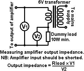
For fun, I tried out a variant on merlinb's method with the transformer (which is, itself, essentially the same method jcx was talking about). Rather than connect the primary to the mains supply, I connected it to a signal generator. (Amongst other things, it has the advantage one can test the impedance at other frequencies, and not just at 60Hz or 50Hz.) Within experimental accuracy, it gave the same answer I was getting from the resistor plus paralleled resistor method. (About 0.8 ohms for the OTL I was trying it with.)
By the way, I don't think you said what test equipment you have. Presumably you have a meter (DVM?) that can measure AC voltage? Do you have a signal generator? I think it would be much better to do your measurements using that, rather than white noise. If you don't have a signal generator, I am guessing that you can probably find sinewave signal sources as mp3 files on the web somewhere.
Chris
yes, I am a little short on equipment, although I have a good audio oscillator, I'm waiting till next week to drag it out and use it for a precise freq sweep. My FET volt/ohmmeter is acting strange, so I need to get a new one, am using the old standby V/O from when I had the tv shop, which is fine for nearly all needs. Never really liked the DVMs as they aren't useful in hunting intermittents....so far, it's working great with an incompletly tubed output stage, once having gotten control of distortion in the driver stage...took an extra 12BH7 to deliver enough voltage to the grid rails....the heat method is more of an intellectual excersize than any serious measurement, unless I spend alot of money getting research grade thermocouple components and spend another whole month getting all that figured out...but as a ballpark estimator, I think I found a neat trick.....at least new to me..maybe someone has done this before? The front end I'm using is a modified grommmes 260A design...DC coupled all the way to the output stages...one problem I had to overcome was that it had too much gain...you could have plugged in a mag phono and done alright, but for a basic amp, too high, so I switched the 100K plate supply to the 12AU7 from+250 to the plate of the driven phase splitter,which has about 190 volts, plus delivers huge amounts of neg feedback to the stage...I will probably modify this later, doing a partial pull-up to the regular +250 and increase the resistor value back to the 12BH7 plate. That will be a later on tweak to equalize the gains in the phase splitter sides...right now, the grounded grid side has more gain in the other..which is opposite of normal...and I've been thinking it's possible to do a completely DC to DC amp all the way to the speakers....by running the driver stage with a neg supply to cathodes and grounding the normal B+....I'm running the 6550 grid rails at about -24 volts, so this seems doable. Haven't plotted it out yet..so it's kinda speculative...pretty cool idea though...definitely would have to put in fuses to the speakers along with some kind of infrasonics-limiter...
hello all. would like to report on circlotron progress. I got my 6-6550s yesterday and found as the power in the output stage increased, up from four tubes to six, certain problems of instability cropped back up that I thought I had already addressed ....seems I had, but only with fewer watts to deal with. So I began going back over screen supplies and how they're worked out. I had simply tied them together and hooked them to respective plate rail with a single 120 ohm, so I hooked screens to respective plates with 150 ohmers, and tied the two sides together with a common screen rail,using 120 ohmers to the screen end of each 150 ohm, so as to give back and forth neg feedback. Tying the screens to the opposite bank as some diagrams showed proved undoable, causing large spurious voltage swings on bass notes. So, I was glad to figure out a way to re-introduce neg feedback into the screen ckt....as an early concept was, the more neg feedback, the lower the impedance. So, things were better, less large excursions, but as one problem is solved, others become more apparent... some intermodulation distortion was easily heard on certain musical passages, but not on others. From the beginning I had been suspicious of the idea of grounding the cathode rails with 1K ohmers, so I began to wonder if that was part or all of my problem...then I realized that the only "grounding" that needed to be done was from the last driver stage (12BH7) to the output stage cathodes...so I removed the 1Ks from chassis and ran them back to the cathodes of the driver...with has about +5 on the cathodes...first I hooked them up to their respective driver stages and got a huge howling when tentatively powered up. Quickly unplugging, I switched the 1Ks to connect to opposite driver cathodes and cautiously plugged in....unbelievable...my instability problem was gone, my intermodulation problem gone, and the neg feedback with this arrangement, lowered gain,(which was still too high anyway), down to a perfect level for a basic amp. My volume contol on the preamp sets nearly identically as with the mac hooked up...so I was pretty happy with the results, it now sounds like a "real" amp. I went ahead and put .47 mfd caps in series with the 1Ks, just to prevent any problems with the +5 volts on the cathode, and nothing changed. Now I was seemingly making real progress at making a practical OTL amp using conventional tubes, that doesn't require more than 6 output tubes per channel. I did re-wire my bose 901s to series, got the impedance up on both systems, seriesed those, now have 128 ohms of load. O course, this doesn't include the sub, so I took a 500 ohm gen replacement xfmr and hooked it up to the plates, using that to drive the sub. So as it stands now, I have a quasi-otl system, with the mains hooked up directly to cathode rails, the sub transformered off plate rails, (with appropriate low pass filter). I am hooked now on this OTL concept as it DOES sound better. Even just having a monoblock hooked up, the music has an intresting quality of seeming to materialize about a foot of so in front of the speakers.....the increased clarity of not being squeezed thru a xfmr. seems a real phenomenon..can't wait to build another for stereo. Now that most of the main parameters have been addressed, it shouldn't take another whole month to build. Now all I need is 7 more EV-300 18" per side to get the impedance of the subs up to 64 ohms, which should be a close enough impedance match to hook up in a customized crossover, everything running off the cathode rails, then the system will be full OTL.
Last edited:
have hooked up both subs in series (16 ohms) and used a low pass inductor in series with a 120 ohm resistor, giving a net resistance of 136 ohms and hooked this up to the plate rails...elimnating the 500 ohm transformer, getting to a pure OTL system. You would think that having the 120 ohm in series with the subs would kill output, put strangely, doesn't...I guess as the closer impedance matching somewhat compensates for power loss...anyway, the real intresting thing is that there appears to be some natural crossover qualities of the OTL....as I removed bass information from the plate rails, it seems to dissaapear in direct proportion from the cathode rails....I havent' verified this yet, but will attempt to do so shortly. This would mean, if a real effect, the boses can be alone on the cathodes with no high pass filter required, the selective loading on the plates with the low pass load seems to elimenate this need...leaving only the low pass inductor to funtion as a complete crossover. Even if the "natural crossover" effect doesn't pan out, removing the xfmr has vastly improved the bass detail. Only drawback now is that sub feed is at +170.
today I worked to get more neg. feedback in the output stage. The diagrams I've seen usually have a 100K resistor between plates and grids, I hadn't tried that yet, waiting to get all the other basics done. Upon adding the 100Ks immediately the bias swung way too positive, beyond the range of correction with the 5K bias contol. Further trials hit upon a 2.2 meg being high enough to allow the controls to give the minus 16 neg bias. This seems to have stabilized the output even more, as now the bias control voltage range seems expanded....before there was a rather limited range of bias voltages between cutoff and saturation distortions...now the cutoff distortion seems to occur with more reverse bias than previous, and the foward bias distortion seems to have dissapeared at the previous voltage observed without the 2.2 meggers. I didn't leave in foward bias for long so as to protect the tubes, but the functional range of bias voltages seems to have increased, making the output stage much less subject to "under and over" distortion, the control setting is much less critical. I've read about the bias matching problem some bloggers have reported, to the extent of placing center-null meters on the front to keep an eye on that. With so many of those giant russian triodes in their amps, probably not a bad idea...but with 6 standard outputs, that problem doesn't exist. I zero the voltage at the cathodes in the morning, that evening it reads within a few tenths of zero. I will go back into the bias circut later with the goal of being able to lower the 2.2megs down toward the 100K shown online...will have to go back in an re-jigger the bias feed resistors, to compensate for more + coming in from the plates...will report on that tommorow. Another good thing is that the tubes run suprisingly cool...I can touch them and they're not overly hot. In fact, they run cooler than if they were in the macintosh 275. A friend is bringing down some sa-cds to see how they do. I don't have any sa-cds yet, but have noticed some cds have a "fringey" high end, I guess because of lower sampling standards....kinda like mp3s which I never go into. I still like vinys as the high end seems a little sweeter. Another thing I've noticed, running the preamp in mono mode, is a shrillnes in some cd's midrange, that isn't there when set back to stereo. On
dylan's "Modern Times" cd I noticed this more than others...at first I thought it was the amp. Upon flipping the preamp back to stereo, the harshness went away...his voice is getting pretty harsh anyway, so I,m happy to hear he's doing better again...haha...
dylan's "Modern Times" cd I noticed this more than others...at first I thought it was the amp. Upon flipping the preamp back to stereo, the harshness went away...his voice is getting pretty harsh anyway, so I,m happy to hear he's doing better again...haha...
- Status
- Not open for further replies.
- Home
- Amplifiers
- Tubes / Valves
- amplifier output impedance measurement