Thanks for the link . Bob Cordell shows b to c caps being used , except in a zorbell configuratation 220pf with 47R on both o/p trannies ( page 208 of his amp book ) , in combination with base stopper resistors .
Ref changing chip supply position.......you might have only marginal stability and the chip supply is increasing open loop gain assuming it supplies a higher voltage or it could be a rail decoupling issue .
PS did you ever try your configuration more like SELFs original , ie without the top constant current.........mind you you would still have had stability problems caused by using the TIPs.
Just looked it up in Cordell's book, it was in a triple configuration. At least this is relatively easy to add to the PCB so I could live with it.
Open loop gain increasing due to higher supply voltage sounds reasonable.
Biasing with only resistor-LED-resistor was also tried but didn't stop the oscillations.
Open loop gain increasing due to higher supply voltage sounds reasonable.
Biasing with only resistor-LED-resistor was also tried but didn't stop the oscillations.
Was just seeing if that was your starting point when you first bread boarded........ and found you had problems with it . ! wasnt suggesting it would be any more stable.
Yeah it is a triple but believe same reasoning applies , as you have already discovered.
Yeah it is a triple but believe same reasoning applies , as you have already discovered.
Suggest have a look at page 86 Cordell , Miller compensation . Though you cant apply it the same way it gives an explanation .
Reading between the lines...please confirm that the 10K and 150 pF change cured the oscillation problem...assuming that this is true, here's the explanation. The cap returns enough high-frequency (fast) feedback from the output of the opamp back to its input to bypass the slowness of the output stage, keeping the amp stable. The combination of the R and C set where the break-point is between feedback taken from the output of the transistors and the output of the opamp. In this case, it's at about 100 kHz. As you get braver, you can diminish the resistor by degrees to see where the edge of stability occurs.
Your point about the 6800 uF cap is a good one...until the amp is stable, keeping the cap is probably a good idea to prevent more damage. Hopefully, once things settle down, you won't need it.
Could you post quiescent current measurements for the output transistors with the load disconnected? That might be interesting to know.
Last edited:
An aside, which is not the root cause, but op-amps in general have bypassing to ground from each supply pin.
hope this helps
-Antonio
hope this helps
-Antonio
It did not work djoffe. So far the only thing that eliminated the oscillations at higher supply voltage is the capacitor across the NPN's B-C terminals.
With two 47p caps across the base-emitter terminals of both output transistors, it no longer oscillates even without the compensation cap.
With two 47p caps across the base-emitter terminals of both output transistors, it no longer oscillates even without the compensation cap.
Last edited:
I'm glad you found something that works!
Do you have a scope to look at the oscillation frequency when it oscillates?
Do you have a scope to look at the oscillation frequency when it oscillates?
Yes I have a scope but no experience using it; will play around with it tonight.
Quiescent current is 4.3mA (voltage across emitter resistor was measured).
Quiescent current is 4.3mA (voltage across emitter resistor was measured).
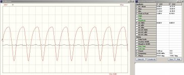
Here is an oscillogram of the oscillation. I have tried pretty much everything now
-better decoupling from V+/V- to ground
-smaller bias resistor on the op-amp non-inverting input (27K instead of 100K)
-base stopper resistor (47R) at transistor bases
-stopper resistor (100R) directly at the op-amp's output (first and second stage)
Unless you have any more suggestions I'm about to scrap this project 🙁
Attachments
I looked up the Darlington output devices. They are quite slow...slower than I had thought before looking them up.
If you go back to post 18 configuration, and change the 150 pF we added to 1.5 nF, things should become stable unless it is complaining about the lack of an output inductor. Of course, if it does make things stable, you'd want to back the value down a bit, but first...get it stable.
There are a few other worrisome things...
1. Your bias current in the output stage, if still 4.3 mA, is a bit low. 40 mA would be better.
2. Most amps will complain (oscillate) without the output inductor...some loads will be happy, some loads won't.
3. your C in the zobel is a bit low, and your R a bit higher than usual.
Does the amp oscillate with load attached? without load attached.
Recommended:
try the 1.5 nF change first, then look for oscillation with and without the load in place.
Good luck!
Ah sorry I'm an idiot! Forget about that oscillogram.
I was replacing parts all the time to check if they were damaged. The emitter resistors I put in however were out of the parts bin. During breadboard experiments I had burned up a few output transistors and didn't make sure to dispose of the emitter resistors along with the zapped transistors. I checked them with a multimeter before soldering but it appears they have some subtle damage that occurs only with a certain current flowing through. The multimeter showed the correct resistance but once in the circuit they caused terrible distortion and/or oscillation. Putting a wire across the emitters immediately made things quiet. I now replaced them with new, never used before resistors and the output oscillation is gone; there's just 3-5mV RMS of noise. Also listened to some music and now it finally sounds okay. CComp of the second op-amp is 270p now; with only 47p the music sounds grainy as if some low-frequency oscillation is taking place.
I just ordered a large SMD 1206 resistor sortiment to have more values to play with. What values would you recommend for the zobel network? Can you give a recommendation on the output inductor as well? Should I use a ferrite type of inductor or just a few windings of copper wire?
classic zobel values are:
R=4.7 to 10 Ohms, C=0.1 uF
For the inductor, air core would be best. Something around 10 uH, paralleled by a 10 Ohm resistor.
So...can you post the latest schematic?
R=4.7 to 10 Ohms, C=0.1 uF
For the inductor, air core would be best. Something around 10 uH, paralleled by a 10 Ohm resistor.
So...can you post the latest schematic?
- Status
- Not open for further replies.
- Home
- Amplifiers
- Solid State
- Amplifier oscillation problem