Hi all,
first of all: I'm a newbie to amplifier design/analog electronics in general so bear with me for my stupid questions 🙂
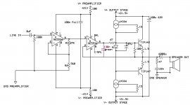
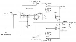
I've built a stereo version of the attached amplifier schematic. The idea is an adaption of Douglas Self's headphone amplifier (chapter "Driving heavy loads" in "Small signal audio design"). The amplifier oscillated badly (loud hissing/hum). On the breadboard version I built first this could be "solved" by putting two 100R resistors in the supply rails of the op-amps. This I discovered by accident only. Now the PCB is etched and soldered and it has even worse oscillation noise with the two 100R resistors still in place. After lots of trial and error I found out the oscillation can be cured with a 130n capacitor between IN- and OUT of the second (voltage follower) op-amp. 22p, 47p and 270p capacitors at pins 5 and 8 of the second NE5534 were also tried but to no avail.
I don't have enough theoretical knowledge to understand what is going on here, and I don't know if this capacitor makes any sense technically. At least it makes the audible oscillation go away. The original Douglas Self schematic uses no frequency compensation at all. Any suggestions?
Best regards,
macplauder
first of all: I'm a newbie to amplifier design/analog electronics in general so bear with me for my stupid questions 🙂
I've built a stereo version of the attached amplifier schematic. The idea is an adaption of Douglas Self's headphone amplifier (chapter "Driving heavy loads" in "Small signal audio design"). The amplifier oscillated badly (loud hissing/hum). On the breadboard version I built first this could be "solved" by putting two 100R resistors in the supply rails of the op-amps. This I discovered by accident only. Now the PCB is etched and soldered and it has even worse oscillation noise with the two 100R resistors still in place. After lots of trial and error I found out the oscillation can be cured with a 130n capacitor between IN- and OUT of the second (voltage follower) op-amp. 22p, 47p and 270p capacitors at pins 5 and 8 of the second NE5534 were also tried but to no avail.
I don't have enough theoretical knowledge to understand what is going on here, and I don't know if this capacitor makes any sense technically. At least it makes the audible oscillation go away. The original Douglas Self schematic uses no frequency compensation at all. Any suggestions?
Best regards,
macplauder
Attachments
Welcome to the world where amplifiers oscillate, and oscillators don't.
A few problems here:
1. running NE5534 on +/- 21 or 21.5 makes me a bit nervous (but isn't the real problem)
2. second stage as shown will never be stable...you have essentially unity feedback, and 5534 isn't unity gain stable without comp cap.
3. wrapping the slow output stage round the opamp is another recipe for instability.
4. some of the bypassing, makes me a bit nervous, but ...the real issue is loop gain problems.
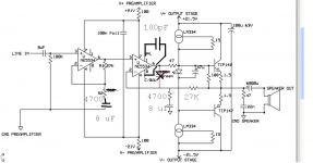
I've enclosed a reallocation of the gain that should make things a lot more stable.
Note too, that, the
1. 6800 uF output cap is probably superfluous.
2. you'll probably want to add some caps in the earthed end of the feedback to help eliminate dc offset at the output
3. you're living a bit dangerously without an output inductor.
4. the zobel values look a bit higher r and lower c than typical
My value changes are reasonable guesses...they might not get you all the way to stable, but I think it should go a long way. (I defaulted some things to values you already have).
A few problems here:
1. running NE5534 on +/- 21 or 21.5 makes me a bit nervous (but isn't the real problem)
2. second stage as shown will never be stable...you have essentially unity feedback, and 5534 isn't unity gain stable without comp cap.
3. wrapping the slow output stage round the opamp is another recipe for instability.
4. some of the bypassing, makes me a bit nervous, but ...the real issue is loop gain problems.
I've enclosed a reallocation of the gain that should make things a lot more stable.
Note too, that, the
1. 6800 uF output cap is probably superfluous.
2. you'll probably want to add some caps in the earthed end of the feedback to help eliminate dc offset at the output
3. you're living a bit dangerously without an output inductor.
4. the zobel values look a bit higher r and lower c than typical
My value changes are reasonable guesses...they might not get you all the way to stable, but I think it should go a long way. (I defaulted some things to values you already have).
Attachments
Thank you for your suggestions, they are much appreciated! 🙂
I will try out your suggestions tomorrow, right now I'm tired and sick of the circuit after fighting with the oscillation problem the whole day 🙁
Before I start cutting PCB tracks I have a few questions regarding your reconfiguration of the gain:
-does the second stage bring any benefit over a single stage with equivalent gain? Mr. Self's argument for the second (follower) stage was that it has maximum feedback to fight distortion. I figure this is no longer the case if a feedback network is used, so why not just throw out the second op-amp (its in a socket anyway) and let the first one do all the work?
-is there like rule of thumb with minimum gain required to drive a slow output stage like this with an NE5534?
Thanks again for your support.
The original configuration, if stable, had the advantage of potentially lower distortion. In that configuration, the stage with all the gain, the first stage, was lightly loaded, e.g. the noninverting input of the second stage, so should behave quite well.
The second stage, in a unity gain config, has max feedback. If stable, it would make for lowest distortion. There is a finesse you can do, where you can tailor the feedback network to leave maximal loopgain in the audio band, and tailor the gain in the ultrasonic region to achieve stability.
After you report on your progress and how the mods went, perhaps I can give you some practical values for the finesse.
If you're trying for high performance, the rules of thumb are typically too broad to maximize performance. It really comes down to feedback theory and the Nyquist stability criterion, and loop gain measurements. Still, there are ways by simulation and lab test that you can iterate in to a pretty optimal solution.
Finally, there's one other potential issue for the original design...at high output swings, you may be driving the second stage's input outside of its rated common mode range, or at least, be causing common mode distortion that negates the benefit of all that feedback.
I would eliminate the second NE5534, and the top LM334.
The 100K input bias resistor is too large for the input bias requirements of the NE5543, I would try 27K instead.
I would eliminate the 100Ω resistor on the TIP142.
I would add 10µF+0.1µF on the ±V rails to ground as close to the opamp as possible.
It may be possible to reduce the series 100Ω to around 10Ω, or even eliminate them.
I would add 22µF on the ±V rails for the outputs with the grounds as close as possible to the speaker grounds.
I would use some sort if resistor in series with the input, try around 1K.
I would add a cap to ground after the input resistor, try values in the range of 100pF~1000pF.
Move the 47Ω resistor into the base of the TIP142, and add one to the TIP147.
Decrease the 47Ω on the output zobel to 4.7Ω, you may also have to increase the cap to 47nF.
You will need a cap in series with R2 (to keep the input bias and DC off-set low), 270µF+0.1µF would give have a 1hz pole.
R1 now goes to speaker out, we may need a cap in the range of 10pF~100pF in parallel (with a resistor of about 2.7K in series with it).
A compensation cap may be needed on the NE5534 compensation pins.
Last edited:
"3. wrapping the slow output stage round the opamp is another recipe for instability."
No, if the opamp is slower than the output it will add stability (if the opamp is stable).
No, if the opamp is slower than the output it will add stability (if the opamp is stable).
What you have mainly done to upset Douglas Selfs cct is put complementary power o/p devices ( high capacitance ,high hfe ) in circuit where he had small signal transistors (low capacitance , power of 10 lower hfe ) . This results in much greater phase lag to the point of oscillation .
Suggestion :- if i had got to the point of having built pcbs i wouldnt want to start altering them drastically till i had to.
Try starting with base stopper resistors as suggested by djk ie move the 47R to right near the base of the TIP and add another one to the base of the other TIP ( see page 72/3 Emmitter-follower stability, small sig audio design ).
Put the cap on pins 5 and 8 on the o/p 5534 as tried previously.
Decouple the 100Rs on the 5534s side with 100uF jockied by 0.1uF each side to earth , not rail to rail ( 0.1 as close to pins as practical)
Remove 130nF and see if it still oscillates.
Last edited:
PS :- by adding the 130nF you have tailored off the frequency response before the phase lag causes a problem .Apologies for the edits.
Thanks again for the valuable input, this is a great forum!
I have now tried the modified circuit by Djoffe by throwing out the second-op amp all together so that the first one drives the push-pull stage directly. The 100R resistor between the op-amp output and speaker output was also removed. The amplifier now does not oscillate audibly without input signal applied. At a very low level input the amplifier sounds more or less ok, but at slightly higher levels a loud hissing/ticking appears. I had similar noises before when one of the emitter resistors burned out and basically one half cycle of the output waveform was missing. The resistors are perfectly ok tough. The op-amp is compensated as suggested. I did not include the DC blocking cap in the feedback path as suggested by DJoffe because this would require very nasty modifications of the PCB. It might not be possible at all to fit a resonably sized capacitor in there. Could the oscillations be caused by DC offset?
Btw the voltage over the output cap is about 1.5V.
Base stopper resistors (47R) were also added (SMD 1206) to the bottom side to the bases of both transistors.
I have been trying different modifications for at least 20 hours now and also resoldered completely new parts to rule out that any damaged semiconductor causes these oscillations. I'm starting to think that the problem is in a whole different place. The amplifier was running perfectly fine in the exact same configuration as posted originally when I had it on the breadboard. I used it for several month on a daily basis to listen to music. There was never even the slightest hint of an oscillation. With my Beyer Dynamic headphones the sound was always perfectly clear. The problems started to crop up as soon as it was moved onto a PCB. It seems resonable to assume that the problem comes from the PCB and not the circuit, altough the configuration is prone to unstability as pointed out.
Some ideas of what else could be causing these problems:
-supply voltage: The recommended supply range for the NE5534 is +/-15V. The amplifier was running at less than 2 volts below the maximum rating. To rule out the possibility that the opamp itself becomes unstable I dropped in a OPA551 which works up to +/-30V. It still shows the exact same problem. I also run the NE5534 version from a lab power supply at +/-12V and it showed similar oscillations. They would only occur at higher input levels.
-soldering: The TIP142/TIP147 are soldered directly to the PCB with the legs shortened and the soldering joint about 8mm below the casing. I have a suspicion that I keep damaging the transistors when I solder them to the PCB. If this is the case then they must be mounted without soldering somehow. They have to go in the exact place allocated on the PCB in order to fit on the predrilled heatsink.
-bad PCB: Maybe there are some invisible high impendance paths due to incomplete etching.
-other damaged parts: Maybe one of the decoupling capacitors is bad. This sounds far-fetched tough; all caps are rated at 60V.
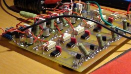
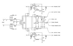
I have attached a picture of the PCB recorded when it was fully populated. It has 5 channels for a surround system. Now only 1 channel has the op-amp and transistors soldered in place; all other channels were stripped of any active components. The power transistors are mounted on the bottom side where they can be mounted on a massive heatsink. The switching relais are not connected to the signal path yet and should not be causing any problems.
The next thing I will try is to solder new TIP transistors with the legs unshortened and an alligator clip connected as a heat sink.
I have now tried the modified circuit by Djoffe by throwing out the second-op amp all together so that the first one drives the push-pull stage directly. The 100R resistor between the op-amp output and speaker output was also removed. The amplifier now does not oscillate audibly without input signal applied. At a very low level input the amplifier sounds more or less ok, but at slightly higher levels a loud hissing/ticking appears. I had similar noises before when one of the emitter resistors burned out and basically one half cycle of the output waveform was missing. The resistors are perfectly ok tough. The op-amp is compensated as suggested. I did not include the DC blocking cap in the feedback path as suggested by DJoffe because this would require very nasty modifications of the PCB. It might not be possible at all to fit a resonably sized capacitor in there. Could the oscillations be caused by DC offset?
Btw the voltage over the output cap is about 1.5V.
Base stopper resistors (47R) were also added (SMD 1206) to the bottom side to the bases of both transistors.
I have been trying different modifications for at least 20 hours now and also resoldered completely new parts to rule out that any damaged semiconductor causes these oscillations. I'm starting to think that the problem is in a whole different place. The amplifier was running perfectly fine in the exact same configuration as posted originally when I had it on the breadboard. I used it for several month on a daily basis to listen to music. There was never even the slightest hint of an oscillation. With my Beyer Dynamic headphones the sound was always perfectly clear. The problems started to crop up as soon as it was moved onto a PCB. It seems resonable to assume that the problem comes from the PCB and not the circuit, altough the configuration is prone to unstability as pointed out.
Some ideas of what else could be causing these problems:
-supply voltage: The recommended supply range for the NE5534 is +/-15V. The amplifier was running at less than 2 volts below the maximum rating. To rule out the possibility that the opamp itself becomes unstable I dropped in a OPA551 which works up to +/-30V. It still shows the exact same problem. I also run the NE5534 version from a lab power supply at +/-12V and it showed similar oscillations. They would only occur at higher input levels.
-soldering: The TIP142/TIP147 are soldered directly to the PCB with the legs shortened and the soldering joint about 8mm below the casing. I have a suspicion that I keep damaging the transistors when I solder them to the PCB. If this is the case then they must be mounted without soldering somehow. They have to go in the exact place allocated on the PCB in order to fit on the predrilled heatsink.
-bad PCB: Maybe there are some invisible high impendance paths due to incomplete etching.
-other damaged parts: Maybe one of the decoupling capacitors is bad. This sounds far-fetched tough; all caps are rated at 60V.
I have attached a picture of the PCB recorded when it was fully populated. It has 5 channels for a surround system. Now only 1 channel has the op-amp and transistors soldered in place; all other channels were stripped of any active components. The power transistors are mounted on the bottom side where they can be mounted on a massive heatsink. The switching relais are not connected to the signal path yet and should not be causing any problems.
The next thing I will try is to solder new TIP transistors with the legs unshortened and an alligator clip connected as a heat sink.
Attachments
> if the opamp is slower than the output it will add stability
Yes. But TIP142 is a slow device.
It is a large power device plus a driver in Darlington connection.
There's no Ft spec (which is iffy on a Darlington) but the sum of turn-on and turn-off times is 5 microseconds which suggests it won't do 200KHz well. Better because emitter-follower. Not that much better because a Darlington's fall-off approaches 12db/oct and assured phase trouble.
I suspect the TIP142's power side is a Ft=6MHz part. hFE is unity at 6MHz and maybe 30 at 200KHz. The fall of hFe is equivalent to a capacitor across the 5534's output, and an extra slope in the open-loop response.
NE5534 has risetime 100X faster, and GBW of 10MHz (10,000KHz) using the internal compensation.
The internal compensation is claimed good for gains of 3 or higher. In fact 5534 is "sometimes" stable at unity gain. This is as safe as using lumber at 3X the code-table strength. It may or may not fail.
Using "FAT" power devices like this instead of the small fast devices Self suggested is (as epicyclic says) a mis-match and not easily compensated. You could raise the closed-loop gain or slug the 5534 with an enormous compensation cap. I suspect this will leave you shy of NFB at 20KHz, and maybe low on slew-rate.
One thing thats been gnawing away at me from the start is the use of 2 constant current sources in the same DC path .Which one is actually in control ! . Could you replace one with a 4K7 resistor or 3K9 and see if it makes any difference . Whats the volt drop across the LED is it about 2.6V and could you measure the volt drops across both 1R5s.
I don't see that as much of a problem, any difference in current will simply be supplied by the opamp.
But PRR's right on the money, big Darlingtons at low quiescent current are definitely on the slooow side of things. A green LED should just be adequate for getting the affair into AB mode, but hardly any further. fT is likely to be relatively modest. (Funnily enough, when you get into class B territory the affair can become so slow that it gets stable again. Found that when simulating a similar amp using these devices. An ohm or two of output series resistance don't hurt.)
Honestly, for a headphone buffer I wouldn't use anything much bigger than a BD139/140 combo or thereabouts. And run them warm, 5-10 mA min, with Class A operation at 50-100 mA not hurting (adequate heatsinking required, of course). These are TO-126 parts though, I'm not aware of reasonably fast, inexpensive medium-power transistors in TO-220 that could serve as drop-in replacements (with other emitter resistors, of course, roughly 15 ohm for class A). The ~3 MHz fT on a TIP31C may or may not cut it when given enough current to work with. BD139/140 are at least an order of magnitude faster. You'd probably need a whole bunch of those to drive a speaker though, and that would require some attention to their capacitance.
Here I'd reduce emitter resistors to maybe 0R47, and if that doesn't give ~30 mA of bias current, use a blue LED.
Last edited:
We're getting closer to solving this riddle 🙂
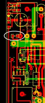
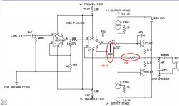
Today I resoldered the power transistors again which didn't change anything. The desoldered TIP's were measured to be ok so device failure was not the problem. Then both LM334 current sources were replaced by resistors, which did't help to remedy the oscillation. Then I soldered a 100R resistors *directly* to the output of the op-amp. It occured to me that this is actually the only difference between what I have on breadboard and what is on the PCB: The breadboard version had 47R resistors right at the op-amp outputs whereas the PCB version had them right at the transistor bases. I've attached a pic of the (ExpressPCB) layout with the resistor marked with a white circle. It crosses the positive supply rail (on the bottom layer) - don't know if that is of any relevance concerning the instability.
A 47p capacitor between B and C of the NPN also had a big effect, eliminating the oscillation noise, but some "wrongness" of sound was still audible.
@epicyclic:
The idea with the two current sources comes from TI's "op amp booster designs" appnote:
http://www.ti.com/lit/an/snoa600a/snoa600a.pdf
Replacing one or both LM334 current sources with a resistor had no discernible effect - without the "base stopper" (or rather "op-amp stopper") resistor it still oscillated badly.
@sgrossklass
There is some space allocated right below the LED for an optional resistor or diode to spread the bias voltage further. What do you think would be better:
-blue LED
-green LED with another LED in series
-green LED with additional resistor in series?
Btw. this circuit isn't driving headphones. It was driving my Canton home theater setup happily - while it was still on the breadboard 🙂
I will now try the original two-opamp configuration again to see if it can be fixed with the stopper resistor as well.
Just a short update: Seems to work fine now in the original configuration with the 100R soldered as close to the first op-amp's output as possible. The second-op amp has a 47p compensation cap between pins 5 and 8.
The first and second op-amp are connected through a wire bridge about 6 inches long. Could that be the problem here?
The first and second op-amp are connected through a wire bridge about 6 inches long. Could that be the problem here?
Another update: It looks as I was cheering too soon 🙂
The amplifier does look stable now but only with the op-amps powered from the main supply rails. I just connected them to the regulated +/-21.5V power supply and it became unstable again. With the 47p capacitor on the TIP142's base and collector it sounds decently ok.
Pardon my noob question, but is a base-collector capacitor on the output transistors a legitimate cure for oscillations?
Attachments
Last edited:
tell us about your "regulated power supply". There were certainly other issues that you have resolved, but, depending on its design, could the regulated power supply be oscillating?
Also...can you post the latest schematic?
Also...can you post the latest schematic?
Schematics attached.
The power supply for the op-amp uses two additional windings on a torroidal transformer to get a little extra voltage to compensate for regulator drop. The regulator consists of 7812/7912 with ground connected to emitter followers that ride a few volts above/below ground to get about +/-21.5V output. Another of Mr. Self's ideas...
Another point I forgot to mention in my previous posts is that the 47u electrolytic capacitor between the transistor bases had also been removed to rule out component damage. Inserting a brand new capacitor again caused terrible noise 🙁
Attachments
unless there are still bypassing issues, the following two components should stop your oscillation troubles, at least if they stem from loop gain, rather than local issues.
It should be, if anything, too stable, but at least this gives us a stable starting point.
It should be, if anything, too stable, but at least this gives us a stable starting point.
Attachments
also...why do yo keep the 6800 uF coupling cap at the output? There will be a little DC owing to the high gain of the first stage and its input offset voltage, but hopefully not too much...and there are more blameless ways to reduce the offset voltage effects on the load.
Thanks. Could you explain what the 10K resistor does?
DC voltage over the output cap now is 105mV. The cap was left in there to protect the speakers. I had quite a bunch of output transistors burned out during my experiments and they always did with a short circuit between collector and emitter (burning out the emitter resistors).
DC voltage over the output cap now is 105mV. The cap was left in there to protect the speakers. I had quite a bunch of output transistors burned out during my experiments and they always did with a short circuit between collector and emitter (burning out the emitter resistors).
- Status
- Not open for further replies.
- Home
- Amplifiers
- Solid State
- Amplifier oscillation problem