Just stabbing in the dark here, but I think that the potentiometer cases should be grounded by their connection to the chassis with their mounting nut. If you have an anodised chassis, you might want to check that you are getting a good electrical connection between pot case and chassis.
Too bad grid stoppers didn't kill the oscillations.
I've done some work on old Marshalls and your build looks very similar. I've always wondered how they managed to be stable with wires running untwisted and w/o gridstoppers. The parallel wires runing from the tagboard to the tubes are just asking for it.
Regarding finding the cause in stead of using gridstoppers. The cause is capacitive coupling between a gain stage and some input, which happens to be >180 degrees different. It's no hokus pokus. Finding excactly where this crossfeed occurs is interesting, but as long as the general layout is good, gridstoppers make a barely stable circuit very stable. Usually a reasonably stable circuit can oscillate when cranked all the way, and grid stoppers provide just enough dampening.
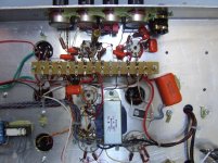
Here is the inside of my latest amp. It has about 80dB of gain in the preamp, and from it's very first turn on, it's been completely good to go. I don't use tagboard for the preamp section, but real point to point with all sensitive gain stages and their resistors as close as possible. I place my preamp tubes around the input and the controls as near the preamp as practical. Star grounding is very important as well, though many amps use bus ground as in your build.
Building like this, point to point, and short connections, has made my amps work every time w/o any surprises. Except when I've forgotten to ground something, like the secondary of the OPT or something else, but as soon as I find the missing gnd, all is well.
I'm at loss of more advice. I don't like the wires (parallel and too long) or the gnd bus, but as mentioned, that's how many amps are built, so I have no right to say that it is wrong.
I really hope you find the cure soon and don't give up. Though I suspect there are seldom cases where you actually play with the treble all up. Many amps will oscillate at that setting, believe it or not. Some guitars make an amp oscillate at lower gain settings than other guitars. It's what gives instruments and their amps 'character'.
Good luck mate.
I've done some work on old Marshalls and your build looks very similar. I've always wondered how they managed to be stable with wires running untwisted and w/o gridstoppers. The parallel wires runing from the tagboard to the tubes are just asking for it.
Regarding finding the cause in stead of using gridstoppers. The cause is capacitive coupling between a gain stage and some input, which happens to be >180 degrees different. It's no hokus pokus. Finding excactly where this crossfeed occurs is interesting, but as long as the general layout is good, gridstoppers make a barely stable circuit very stable. Usually a reasonably stable circuit can oscillate when cranked all the way, and grid stoppers provide just enough dampening.
Here is the inside of my latest amp. It has about 80dB of gain in the preamp, and from it's very first turn on, it's been completely good to go. I don't use tagboard for the preamp section, but real point to point with all sensitive gain stages and their resistors as close as possible. I place my preamp tubes around the input and the controls as near the preamp as practical. Star grounding is very important as well, though many amps use bus ground as in your build.
Building like this, point to point, and short connections, has made my amps work every time w/o any surprises. Except when I've forgotten to ground something, like the secondary of the OPT or something else, but as soon as I find the missing gnd, all is well.
I'm at loss of more advice. I don't like the wires (parallel and too long) or the gnd bus, but as mentioned, that's how many amps are built, so I have no right to say that it is wrong.
I really hope you find the cure soon and don't give up. Though I suspect there are seldom cases where you actually play with the treble all up. Many amps will oscillate at that setting, believe it or not. Some guitars make an amp oscillate at lower gain settings than other guitars. It's what gives instruments and their amps 'character'.
Good luck mate.
Attachments
Just stabbing in the dark here, but I think that the potentiometer cases should be grounded by their connection to the chassis with their mounting nut. If you have an anodised chassis, you might want to check that you are getting a good electrical connection between pot case and chassis.
No stabbing in the dark here. Good point.
Could it be the cathode follower part of V2 oscillating? A cathode follower does not like a capacitive load, yet this is almost what it gets when the treble and vol controls are high. The cathode of V2 pin 8 can see the input capacitance of the phase splitter. Try putting a resistor, 1-5 k, at V2 pin 8. Many cathode followers need this, but the circuit does not have it. Putting your 270K in has a similar effect but it is further away so has less effect.
Alternatively, are you certain that the 16uF HT decoupler is OK - not open circuit? Is the ground lead from this grounded?
At first I thought that the problem was capacitive feedback but I now think the frequency is too low for that. I think you have a phase shift oscillator somewhere hidden in the circuit.
Grounding the (preamp) filter caps to the buss is a little strange for me. I've read of grounding each stage's filter to it's cathode-resistor's ground, but bussing with a single wire this way scares me. I'd be thinking about the filters' current possibly modulating something else on the buss. I'd try flying those 2 grounds directly to the grounded end of the buss instead. Even if it doesn't fix it.
The 1st amp I built had massive hum for many moons until I realized I shouldn’t ground the CT of the HV winding of the PT all the way on the other side of the chassis from the filter grounds.
$0.02
The 1st amp I built had massive hum for many moons until I realized I shouldn’t ground the CT of the HV winding of the PT all the way on the other side of the chassis from the filter grounds.
$0.02
Rob --
From your photos, it appears that you have 3 separate output jacks for easy connection and/or change between a 4, 8, or 16 ohm cabinet at will. These appear to be located between (1) the two output tubes, (2) the output tubes and phase inverter, and (3) the phase inverter and mixer/CF tube. I don't know if that is the original design layout, but with an amplifier with this much gain, that is just asking for trouble. If this is as it appears to be, why not try disconnecting the two jacks on either side of the phase inverter, and pull those output transformer leads back away from the small signal tube area and see if the problem doesn't subside. With three open jacks like that (non-shorting that is), there is plenty of possibility for capacitive feedback in that area -- whether a particular jack is used or not. If this is what's going on, grid stoppers ain't gonna help this one! I note the schematic you provided only shows one output jack and an impedance change switch.
Dave
Rob --
From your photos, it appears that you have 3 separate output jacks for easy connection and/or change between a 4, 8, or 16 ohm cabinet at will. These appear to be located between (1) the two output tubes, (2) the output tubes and phase inverter, and (3) the phase inverter and mixer/CF tube. I don't know if that is the original design layout, but with an amplifier with this much gain, that is just asking for trouble. If this is as it appears to be, why not try disconnecting the two jacks on either side of the phase inverter, and pull those output transformer leads back away from the small signal tube area and see if the problem doesn't subside. With three open jacks like that (non-shorting that is), there is plenty of possibility for capacitive feedback in that area -- whether a particular jack is used or not. If this is what's going on, grid stoppers ain't gonna help this one! I note the schematic you provided only shows one output jack and an impedance change switch.
Dave
Eagle eyes Dave! Not sure if that is going to be the problem, but... It looks like Rob is using that jack between V2 and V3 to feed to his dummy load.
Eureka
OK Folks,
Finally got to the bottom of the problem.
Tried all of the solutions suggested today. Pots are grounded, used the 20pF cap, tried a 3.3K resistor at pin V2, pin 8, changed the signal earth connections around - all no improvement.
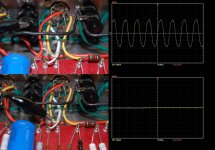
Dave, you hit the nail on the head. The 3 jack option was my (bad) idea. I removed the 16 ohm lead - no noise. As the chassis is laid out this way, I was reticent to remove it unless I had no other option. I used some foil (thanks Wavebourne) and discovered that if the lead to pin 2, V3 was shielded, the oscillation stopped.
Chris, I used your shielded wire to very good effect. Have a look at the first picture to see the results.
Thanks everyone for helping me work through this one. I have learned a lot of important lessons. The importance of layout and how it can cause of capacitive feedback. I really couldn't believe how a simple design issue like this could cause such a significant problem.
Kevin, thanks for your input, I have learned that all grids should have grid stoppers. They remain in place.
Rob
OK Folks,
Finally got to the bottom of the problem.
Tried all of the solutions suggested today. Pots are grounded, used the 20pF cap, tried a 3.3K resistor at pin V2, pin 8, changed the signal earth connections around - all no improvement.
Dave, you hit the nail on the head. The 3 jack option was my (bad) idea. I removed the 16 ohm lead - no noise. As the chassis is laid out this way, I was reticent to remove it unless I had no other option. I used some foil (thanks Wavebourne) and discovered that if the lead to pin 2, V3 was shielded, the oscillation stopped.
Chris, I used your shielded wire to very good effect. Have a look at the first picture to see the results.
Thanks everyone for helping me work through this one. I have learned a lot of important lessons. The importance of layout and how it can cause of capacitive feedback. I really couldn't believe how a simple design issue like this could cause such a significant problem.
Kevin, thanks for your input, I have learned that all grids should have grid stoppers. They remain in place.
Rob
Attachments
I'm glad you found it. I am surprised that the oscillation was at so low a frequency.
By following this thread I have learnt something about guitar amps - my background is hi-fi and amateur radio. I never realised that in guitar amps it is routine to solve layout problems by slugging everything with large grid stoppers, so the HF end stops at a few kHz. This may explain why "tube rolling" has such a big effect - a guitar amp is very sensitive to Cag multipled by the Miller effect, as this directly affects the HF roll-off in the middle of the audio band. Trimmer capacitors would be a much cheaper way of tweaking the sound!
By following this thread I have learnt something about guitar amps - my background is hi-fi and amateur radio. I never realised that in guitar amps it is routine to solve layout problems by slugging everything with large grid stoppers, so the HF end stops at a few kHz. This may explain why "tube rolling" has such a big effect - a guitar amp is very sensitive to Cag multipled by the Miller effect, as this directly affects the HF roll-off in the middle of the audio band. Trimmer capacitors would be a much cheaper way of tweaking the sound!
I'm glad you found it. I am surprised that the oscillation was at so low a frequency.
By following this thread I have learnt something about guitar amps - my background is hi-fi and amateur radio. I never realised that in guitar amps it is routine to solve layout problems by slugging everything with large grid stoppers, so the HF end stops at a few kHz. This may explain why "tube rolling" has such a big effect - a guitar amp is very sensitive to Cag multipled by the Miller effect, as this directly affects the HF roll-off in the middle of the audio band. Trimmer capacitors would be a much cheaper way of tweaking the sound!
It's not routine to slug around with grid stoppers in guitar amps any more than in any other high gain circuit. When you have loads of gain, and use the amp at full ahead, the grid stoppers simply make the circuit more stable than w/o. Also many use grid stoppers as part of the amplifier's tone.
That said, there are many bad layouts around, and it is well known that Fender amps (among many other makes) had to be built excactly to plan, even a slight offspring could lead to problems like seen in this thread.
Kudos to Dave for spotting the speaker jack and it's risky placement.
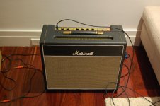
Rob, your combo looks great. No doubt it sounds as good as it looks.
Rob --
Glad you got it going! When I was barely a teenager back in the 60's, I was building Fender knockoffs for our garage band. Through out that time, I learned all the lessons of ground loops, shielding, and the importance of a well laid out physical design (among so many other things!) the hard way -- but they were lessons well learned. No doubt you have learned a lot from this exercise as well. I could only have wished for a tool like the internet back then! You've received such great advice from so many contributors here that the learning curve can be very steep now. Congrats on getting it going!
Dave
It may turn the tube into an oscillator. Feedback from plate to cathode is positive.
QUOTE]
How so?
How so?
By definition. In-phase feedback is called positive, counter-phase feedback is called negative.
the grid stoppers simply make the circuit more stable than w/o.
No. Grid stoppers stop oscillations in real stages with real tubes. Tubes have internal capacitances and inductances, wires have inductances and capacitances, and sometimes such resonant tanks have high enough Q so stages without grid (or/and plate) stoppers oscillate.
I heard many times that high transconductance tubes with grid frames are microphonic. It is not always true: most often they oscillate on very high frequencies.
Congratulations Rob!
Now you have a nice amp, but what is more significant, you may turn around and look from your current position down on your previous experience and knowledge!
Last edited:
Wavebourn, when I say circuit, I mean the whole thing, not just a drawing or the tubes themselves. In a circuit, of course 'real world actual physical working wired up complete circuit', there are resistors, capacitors, component leads, wire, chassis, gnds, b+, inputs, and outputs. All of this gives us possible sources and receivers of capacitive and inductive induced oscillations. Layout is always important, but when the gain is high enough, and for something you want to build many of and get consistent results, grid stoppers simply make that construction more stable.
Plate to cathode feedback is not positive. When the input siganl goes up, the cathode follows. At the plate the same signal will go down, which is opposite, and thus negative. If it were positive feedback, all my amps would be oscillators, they are not.
Placing a small cap from plate to cathode, instead of from plate to gnd, is a rather common tweak in guitar amps today. It used to be a 'secret' or 'magic' trick. Many claim it sounds better than plate to gnd. Granted, when the cathode resistor is bypassed, it no longer matters.
Plate to cathode feedback is positive. A positive signal on the cathode produces a positive signal at the plate - same phase. Putting a capacitor from plate to cathode does not produce positive feedback only if the cathode is already grounded, in which case it is not giving feedback at all but merely slugging the plate.
If you compare a guitar amp with an integrated audio amp with phono input than any guitar amp is low gain! Compare it with almost any radio receiver and it looks very low gain. You need to have a really poor layout to get oscillation, but it seems this is commonplace. It never occured to me that the output might be positioned next to an input stage. Grid stoppers don't necessarily always improve stability because as well as attenuating higher frequencies they also introduce phase shift which can turn negative into positive feedback. Of course if they are big enough then they slow the amp down so much that it isn't fast enough to do HF oscillation, but it then becomes very sensitive to the details of interelectrode capacitances. This is just poor engineering.
For example, putting one of the new (now extinct) Blackburn Tech valves into such an amp would almost double the bandwidth, as they have half the capacitance of a normal ECC83. It would sound very bright, or maybe oscillate.
Pleased you sorted it Rob... you know the old saying 😉
"Amplifiers always oscillate, but oscillators often fail to do so"
"Amplifiers always oscillate, but oscillators often fail to do so"
I love this site, I learn something new every day.
I've always looked at the cathode/plate in relevance to the grid input, and then they move in opposite phase.
I don't use loop NFB, perhaps that's why I've never had problems with large value resistors for grid stoppers? Actually NFB never goes around the preamp, so that's not an issue.
I guess now I need to wire my next amp w/o grid stoppers to check it's stability. I didn't use grid stoppers in the beginning, but over time have come to the conclusion they are a safe bet, besides in my amps they contribute to a HF roll off which is an important part of the tone.
Oh well, I drink alone, and now I use grid stoppers alone...what's next?
I love this site, I learn something new every day.
Oh well, I drink alone, and now I use grid stoppers alone...what's next?
Go and post in Nelsons Pass labs forum.
Class B rules
- Status
- Not open for further replies.
- Home
- Amplifiers
- Tubes / Valves
- Amplifier oscillates - advice sought