I reckon the unwanted feedback pickup point is V2 pin 2. Make sure the 470K is right at pin 2, and screen the lead from the volume pot to it. What is less clear is where the feedback comes from: V3 pin 1 or the output stage. Does the amp still oscillate with the output valves removed?
Grid stoppers are meant to stop VHF parasitic oscillation within one stage. If you have several stages involved, then all big grid stoppers can do is act as low pass filters. They could even make things worse by adding more phase shift. You can kill a 9kHz oscillation by restricting the bandwidth to, say, 4kHz but won't this result in a rather dull sound? At least then you can save money on decent output transformers!
By the way, when you say increasing the volume starts the oscillation do you mean the master volume or the channel volume?
In a way that's good as a x10 probe will only have a few pf capacitance... definitely try the grid resistors as that works in conjunction with the plate capacitance forming a LPF.
I reckon the unwanted feedback pickup point is V2 pin 2. Make sure the 470K is right at pin 2, and screen the lead from the volume pot to it. What is less clear is where the feedback comes from: V3 pin 1 or the output stage. Does the amp still oscillate with the output valves removed?
Grid stoppers are meant to stop VHF parasitic oscillation within one stage. If you have several stages involved, then all big grid stoppers can do is act as low pass filters. They could even make things worse by adding more phase shift. You can kill a 9kHz oscillation by restricting the bandwidth to, say, 4kHz but won't this result in a rather dull sound? At least then you can save money on decent output transformers!
By the way, when you say increasing the volume starts the oscillation do you mean the master volume or the channel volume?
The TMB master volume.
In a way that's good as a x10 probe will only have a few pf capacitance... definitely try the grid resistors as that works in conjunction with the plate capacitance forming a LPF.
Hi Mooly,
Will definitely put these in if the coax solution fails.
Rob
Action number 4 should be performed irrespective of the results of 1,2, and 3😉
Already done.
OK, that is what I assumed.The TMB master volume
It's puzzling that V3 pin 7 has an effect. When VR3 is down this is already grounded by 100nF so I can't see how the probe can change anything.
Another puzzle is that V2a has twice the frequency. This means that frequency halving seems to be happening somewhere.
You could try reducing the 470K grid stopper for V2. Try 220K or 100K. This will probably raise the oscillation frequency, but would confirm that V2 grid is part of the loop.
Sniff for RF (VHF oscillation) I have had similar problems with odd audio tones being randomly generated and in most cases the real culprit is undetected VHF oscillation..
I am not sure what your objection to grid stoppers is, but is a quick fix in most cases with no down side, and IMO is just good ENGINEERING practice.
You seem determined to ignore the suggestions of a lot of people here who have run up against this problem in the past. You can keep spinning your wheels or eliminate one possible cause with just a couple of minutes of work. And if it doesn't work you at least have reached for the low hanging fruit. Seriously the symptoms you describe all point that way.
Of course YMMV...
Last edited:
Sniff for RF (VHF oscillation) I have had similar problems with odd audio tones being randomly generated and in most cases the real culprit is undetected VHF oscillation..
I am not sure what your objection to grid stoppers is, but is a quick fix in most cases with no down side, and IMO is just good ENGINEERING practice.
You seem determined to ignore the suggestions of a lot of people here who have run up against this problem in the past. You can keep spinning your wheels or eliminate one possible cause with just a couple of minutes of work. And if it doesn't work you at least have reached for the low hanging fruit. Seriously the symptoms you describe all point that way.
Of course YMMV...
Hi Kevin,
I am not determined to ignore advice. Not being an engineer, I am sometimes not sure what is and is not good engineering practice. That's what I am here for. I am sure you have read through this thread - several of the members here have made the point that whilst grid stoppers may fix the symptoms, it is better to address the source of the problem. Keep in mind that none of the TMB schematics including the original Marshall design have grid stoppers. Also, I am interested in learning about the problem not just a quick fix. Finally, although it only takes five minutes but in practice if I start on this it will take me a couple of hours and I am leaving it till I have a bit of spare time this WE, so as to rush through it.
Rob
I've explained (I am an engineer and know good & bad engineering practices) you already, that if layout of Marshall amp was well done, they could save few cents per amp avoiding usage of extra parts. If Ampeg SVT has a ground loop in the preamp section, no grid stoppers can help. Especially, to eliminate hum caused by current that charges a B+ filtering capacitor. I've silenced few Ampegs for bass guitarists re-soldering a single ground wire to eliminate hum and couple of resistors to stop HF oscillations in certain positions of timbre regulators.
In your case oscillations happen when highs are boosted up, that suggests most probably capacitive coupling that may be eliminated either by placing some foil between stages, or wrapping some wires in a foil (it needs to be grounded!)
No fancy Teflon isolated shielded wires are needed.
In your case oscillations happen when highs are boosted up, that suggests most probably capacitive coupling that may be eliminated either by placing some foil between stages, or wrapping some wires in a foil (it needs to be grounded!)
No fancy Teflon isolated shielded wires are needed.
Hello Wavebourne, I always appreciate your input and your colourful turn of phrase! 😉
Placing foil around a wire and grounding the wire is essentially the same as using shielded wire? I recommended the teflon shielded wire to Rob, and gave him some to try, not because of any fancy audio properties, I simply find it easier to work with than the stuff that we can get at our local parts supplier. If I slip with the soldering iron, it does not melt the insulation, and it is thin and easy to route, reducing stress on the terminations. As my skill level is not as high as some others here, I need all the help I can get for a neat and functional layout 😉
Cheers,
Chris
I found too that teflon isolated wire is a very good thing for prototyping. However, in case of production only military high-temp condition justifies it's usage. But a foil may look nice as well, especially a thin copper one with one side with conductive adhesive. I had some (bought by chance on ePay), but unfortunately I am out of it, otherwise would ship some in an envelope to a beautiful country of Oz! 😉
Using a foil you may experiment to find which wires have to be shielded. What the point in adding extra capacitances to the ground if they may be avoided, right?
Using a foil you may experiment to find which wires have to be shielded. What the point in adding extra capacitances to the ground if they may be avoided, right?
Last edited:
Wavebourne makes a good point, the grid stoppers were generally left out in the day in order to save a few cents, and they worked very hard to get the layout to the point where the design was reasonably if not unconditionally stable.
Using shielded cable will probably fix the issue by virtue of its significant capacitance. Note that if the original did not use it there may be a small effect on tone.
The reason for using grid stoppers is that it makes the circuit relatively immune from the effects of stray capacitance over which you have little control. It basically reduces the inherent Q of the resonant circuit that exists anytime you have inductance and capacitance in a circuit, in addition at HF the grid stopper isolates the tube's miller capacitance from the external parasitic resonant circuit. Even in an optimum layout these parasitics still exist, they are just below the threshold that creates conditions for oscillation.
Even understanding the problem to the root cause (which I commend despite my previous comments) and fixing it using the traditional layout techniques does not mean that using grid stoppers is a bad idea and they get at the root of the problem.
Wavebourne does make an important point about how things are grounded and this should be looked at carefully. FWIW most Fenders had pretty haywired grounding and they usually (if not always) did not oscillate. (Some did though..)
Can you take a few pix of your build and we can comment on it here. We'll be gentle and this might help those of us trying to advise you understand what the issue might be.
Thanks Wavebourne for the foil suggestion. Unfortunately, I don't have any either.
Hi Kevin, I will post some pictures soon, as the oscillation continues despite my best efforts so far. There is one picture of the layout earlier on in the thread.
Here is what I have done -
1. Replaced all input leads with shielded cables - maybe some improvement but subtle. All shielded earths checked and OK.
2. OT primaries tightly twisted - no change.
2. Grid stoppers on V3. No real difference
3. Grid stoppers on V2 made a significant difference but the amp still oscillates.
So on V2 (both sections) 100K stoppers gave some improvement, 68K was better and 33K was similar to 68K.
4. With grid stoppers in place, I put an an 820pf cap between cathode and plate on V3 - maybe some slight improvement but not significant.
Now have the amp running with 33K grid stoppers on V2 & V3. All other tube including output tubes have grid stoppers. V1 has 68K grid stoppers (always in place) I have removed the 820pF cap as it didn't seem to help.
The oscillation is significantly better. It now only oscillates when the TMB master volume is pushed passed level 9. Surprisingly, the position of the treble pot now seems to make less difference. It still goes quiet when the 'scope probe is placed on pins 2 or 7 of V3.
Any more suggestions - I am thinking of a small resistor (say 10k) between the wiper of the treble and the TMB master volume but ran out of time this morning.
Thanks for the help so far.
Rob
Last edited:
Thanks Wavebourne for the foil suggestion. Unfortunately, I don't have any either.
Can't you buy a chocolate, unwrap it, and use a foil to experiment with shielding? The trick is, just find what needs to be shielded, then use either metal wall between components, or shield a wire. Thin metal mesh may be used as well.
3. Grid stoppers on V2 made a significant difference but the amp still oscillates.
That means something is wrong between V1 and V2. Either ground wired where an output current creates a voltage drop on highs, or wires before V2 have to be shielded. I don't see the schematic now, do you have any potentiometers between V1 and V2?
So on V2 (both sections) 100K stoppers gave some improvement, 68K was better and 33K was similar to 68K.
33K is too much. Keep hunting for parasitic coupling
4. With grid stoppers in place, I put an an 820pf cap between cathode and plate on V3 - maybe some slight improvement but not significant.
It may turn the tube into an oscillator. Feedback from plate to cathode is positive.
Any more suggestions - I am thinking of a small resistor (say 10k) between the wiper of the treble and the TMB master volume but ran out of time this morning.
This is a wise idea.
Can't you buy a chocolate, unwrap it, and use a foil to experiment with shielding? The trick is, just find what needs to be shielded, then use either metal wall between components, or shield a wire. Thin metal mesh may be used as well.
OK we have chocolate wrap and aluminum foil but not copper foil. I have played around with the aluminum foil to shield different wires with no joy.
Reduced the grid stoppers to 3.3K - very similar to the stoppers of higher resistance. Much improved on pre-gridstopper amp but still oscillating.
Have played around with resistors between the wiper of the treble and the TMB master volume. At 270K, problem resolved. I guess that I have just reduced the gain by about 20% - I can live with this solution if I have to as the amp is scary loud and I don't think that I will miss the lost gain.
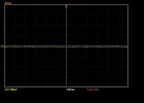
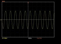
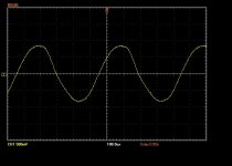
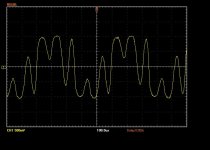
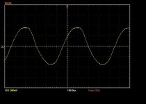
I have attached some trace captures to illustrate the problem.
The pics are as follows -
Picture 1 - No signal, volume set at 9
Picture 2 - No signal, volume set at 10
Picture 3 - Sine wave signal, volume set at 9
Picture 4 - Sine wave signal, volume set at 10
Picture 5 - same as above but with 270K resistor
Attachments
Can you take a few pix of your build and we can comment on it here. We'll be gentle and this might help those of us trying to advise you understand what the issue might be.
Hi Kevin,
Here are some photos. As I mentioned in the above post, the problem is solved with the 270K resistor between the wiper of the treble and the TMB master volume + grid stoppers. This is OK but I lose about 20% gain. If this is the best solution, I can live with it. At the same time, if you spot anything in the photo's that might help to explain the problem, let me know.
You may notice a couple of dead resistors lying in the chassis. Just ignore them, they are old grid stoppers and will be removed. Also, if you look closely you will see an orange wire near a pot which is disconnected. I am aware of that. It was/is connected during testing.
Rob
Attachments
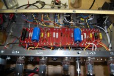
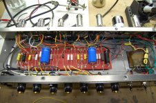
Could it be a grounding problem? Your ground busbar seems to have things connected to it at the nearest physical point, which may not be the best electrical point. I realise that people can often get away with this, but I would give the output stage its own connection to a single common (star) point, and possibly also split the phase splitter from the input grounds. Treat the HT decoupling capacitors as part of the circuit rather than part of the supply. Hi-fi amps are stable with much lower values of grid stopper but they do need to careful about grounding etc.
Your raw gain from V1 grids to V3 anodes is around 1500 so it won't need much signal current in the wrong place to make an oscillator. In addition, the grid stoppers are giving significant phase shift at kHz frequencies, so the phase of any feedback can't be determined just by assuming inversion at each stage.
Your raw gain from V1 grids to V3 anodes is around 1500 so it won't need much signal current in the wrong place to make an oscillator. In addition, the grid stoppers are giving significant phase shift at kHz frequencies, so the phase of any feedback can't be determined just by assuming inversion at each stage.
G'Day Rob. Sorry the shielded wire did not provide the solution for you 🙁
Looking at your description and your solution, I have noticed (as you probably have too) that your problem appears when you have the volume and the treble turned up. From the schematic, this looks like you are getting an oscillation when there is very little series resistance between the cathode follower output at pin 8 of V2 and the grid of V3 at pin 2. Your solution of placing 270k between the treble wiper and the top of the TMB master volume looks like it has fixed the issue. As you are aware, the placement of this resistor changes the voltage divider of TMB master volume, reducing gain. If the problem is gain related, this may be a fix. If it is just a series resistance issue, it might be worth investigating placing some series resistance elsewhere in the circuit between V2 and V3 that does not affect gain (maybe after wiper of TMB master?).
Are the treble and TMB master volume pots close together? If not, try shielding this run.
You say that attaching scope to either pin of V3 stops the oscillation. My Chinese scope probes have about 20pF input capacitance. Would a 20pF or smaller cap from the grid (V3 pin 2) to ground cure the problem. If so, would it do so without affecting the tone? Looks like 20pF with 33k grid stopper should be a corner freq of around 240kHz, so should be OK. I am sure if there is an error in my thinking one of the more knowledgeable forum members will point this out 😉
Good luck!
Chris
- Status
- Not open for further replies.
- Home
- Amplifiers
- Tubes / Valves
- Amplifier oscillates - advice sought