Rob --
No doubt that grid stoppers may solve the symptom, and therefore appear to solve the problem. Your build quality looks very nice, but the problem is clearly feedback that originates from the output tube plates (point of highest gain), back to the input of the afflicted channel. Lead dress and shielding are the real answer. Twist the OPT pri leads, use shielded cable as appropriate, minimize all signal lead lengths, and watch lead dress. Then use grid stoppers if all else fails -- or because you want to, but not as simply a quick fix.
Dave
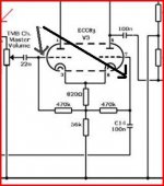
With a string of ECC83 this has high gain and high impedance points. With long unscreened leads this has lots of scope for capacitive feedback. Not surprising that it oscillates. The solution is screening, not just of the cabling to the pots but perhaps also between V2 and V3. Does it still oscillate with the output valves removed? Use a 10:1 probe with an oscilloscope to avoid capacitive loading which might stop the oscillation.
True grid stoppers will not help, as they only affect VHF, unless you are getting beats between two different VHF parasitics. High value grid stoppers will help but, as others have said, they are then just a low pass filter - you can always stop an oscillation by reducing gain.
True grid stoppers will not help, as they only affect VHF, unless you are getting beats between two different VHF parasitics. High value grid stoppers will help but, as others have said, they are then just a low pass filter - you can always stop an oscillation by reducing gain.
Could be feedback from the pwoer supply from output to input.
Passive tone controls rarely have this type of problem.
Passive tone controls rarely have this type of problem.
Rob --
No doubt that grid stoppers may solve the symptom, and therefore appear to solve the problem. Your build quality looks very nice, but the problem is clearly feedback that originates from the output tube plates (point of highest gain), back to the input of the afflicted channel. Lead dress and shielding are the real answer. Twist the OPT pri leads, use shielded cable as appropriate, minimize all signal lead lengths, and watch lead dress. Then use grid stoppers if all else fails -- or because you want to, but not as simply a quick fix.
Dave
Hi Dave,
I agree, I would rather address the problem first rather than a quick fix. I should have used shielded cable. I will rectify this on the WE and see if this fixes the problem. Only if this fails will I move to a grid stopper.
In terms of quick fixes, I suspect that a resistor between the 300pf cap and the treble pot may solve the problem as the oscillation only occurs when the resistance in this pathway is low - however this also falls into the catagory of a 'quick fix'.
I currently have some high quality duel core shielded cable but no single core stuff. Does anyone have a recomendation of cable type/online seller?
G'Day Rob,
I have recently been getting my wire from this ebay seller John's Silver Teflon Wire Shop items - Get great deals on New Arrivals, Micro Drill Bits items on eBay Stores! . Teflon wire is much easier to work with. I use the 20 guage coax for signal runs like this http://cgi.ebay.com/25-20-AWG-Shiel...tem&pt=LH_DefaultDomain_0&hash=item5887fe278b
You probably only need a few inches for the amp? I have some if you want me to drop it around on the weekend and say g'day.
Cheers,
Chris
G'Day Rob,
I have recently been getting my wire from this ebay seller John's Silver Teflon Wire Shop items - Get great deals on New Arrivals, Micro Drill Bits items on eBay Stores! . Teflon wire is much easier to work with. I use the 20 guage coax for signal runs like this http://cgi.ebay.com/25-20-AWG-Shiel...tem&pt=LH_DefaultDomain_0&hash=item5887fe278b
You probably only need a few inches for the amp? I have some if you want me to drop it around on the weekend and say g'day.
Cheers,
Chris
Hey Chris,
Thanks for the wire tip and for the offer - I will be getting quite a collection of Chris donated wire at my place.
Can I take you up on the offer this way - if you have a meter or so, can I pinch it off you and I will order some off ebay and replace your wire when it arrives? That way, I can do some work on it over the long WE and you don't lose any valuable hook-up wire.
Are you around tomorrow? I should be home around midday - let me know if this suits.
Cheers and thanks,
Rob
Just a data point. I did an amp very similar to this. When using 500pf for the top cap in the tone stack everything was fine. At one point I tried a radically different value (I think it was 250pf) and it had a nasty oscillation so it is not entirely unreasonable to experiment with other values of cap as it sure made a difference in my case.
No problem Rob. I am in Perth right now, get home tonight. Around Friday and all weekend.
Cheers,
Chris
Cheers,
Chris
Like I said earlier, one reason for grid stoppers in guitar amps is TONE. In that includes tone controll, or said another way, controll of your amp. The resistor values used in guitar amps is high, often over 100kohms. The effect of such high resistances at the grid is to create a lowpass filter with the input capacitance of the gain stage.
If you don't want to use gridstoppers, try a small value cap from plate to cathode on one of the preamp tubes. 1nF is a good start. I dont think the likees of Dumble or Trainwreck would have included such tweaks if they messed up the tone. On the contrary, they make the tone better.
That said, your amp is not a high-gain type, and with proper lead dress you shouldn't have this problem even w/o gridstoppers. So perhaps do as Wavebourn said and check gnds...
Hmmm. Just checked some schems, and you're right, very few have gridstoppers. I sure use them, and have seldom such problems any more. Of course, it may also be b/c I've got better at lead dress. To me including grid stoppers is part of the tone I get as well as ensuring HF attenuation, and I like the tone, so they are there to stay. The picture of your build shows an inside that is very typical, and shouldn't give you problems.
I would start twisting wires, espescially those with high voltage swings and impedances (such as OPT primary), and generally double check layout and wire dress. Btw to me wiredress includes gnd and how it is connected.
I would start twisting wires, espescially those with high voltage swings and impedances (such as OPT primary), and generally double check layout and wire dress. Btw to me wiredress includes gnd and how it is connected.
Looked at the photo again. The input looks to be on the bottom right? With rather long white untwisted leads to the input tube?
Those should be twisted tightly, or even better be coax. Preferably the first resistor (the 1megohm) and the cathode resistor could be soldered right on the socket. This way the leads from input jack can be twisted tightly the whole way, and terminated with equal lengths as close to teh gain stage as possible.
Btw, it is deff an industry standard to have gridstopper on the first tube, usually 68kohms, but any value from a few k to many k is also common. Even on cheap mass produced git-amps, these are usually soldered right on the socket.
A good read:
Valve Wizard - How to design valve guitar amplifiers
Check the chapter on grid stopper, as well as many other good hints.
Valve Wizard - How to design valve guitar amplifiers
Check the chapter on grid stopper, as well as many other good hints.
Would it be worth looking at the PSU capacitors too?
If the B+ is sufficiently compliant there is a feedback path there too - from the output tube - right back into that cathode follower that drives the tone stack.
If the B+ is sufficiently compliant there is a feedback path there too - from the output tube - right back into that cathode follower that drives the tone stack.
Anything is worth looking at😉 However, powersupplies for guitaramps are traditionally weak, to intentionally give 'sag' in the b+. This is to increase sustain/make the amp compress in a 'natural' way. That's not to say the psu should be ruled out, but just like the tone stack, the problem is probably not there.
Looked at the photo again. The input looks to be on the bottom right? With rather long white untwisted leads to the input tube?
Those should be twisted tightly, or even better be coax. Preferably the first resistor (the 1megohm) and the cathode resistor could be soldered right on the socket. This way the leads from input jack can be twisted tightly the whole way, and terminated with equal lengths as close to teh gain stage as possible.
Btw, it is deff an industry standard to have gridstopper on the first tube, usually 68kohms, but any value from a few k to many k is also common. Even on cheap mass produced git-amps, these are usually soldered right on the socket.
Hi SemperFi,
I do have 68K gridstoppers on V1 and this does differ from the schematic and they are soldered onto the socket. Yes, you are correct about the input lead - horrible in retrospect. I use coax on my hi-fi amps but have no single wire coax in the workshop and figured that as it was a guitar amp (and they are always noisy aren't they?) I could get away with hookup wire. Lesson learned. I am going to address the input leads. Will use coax.
Will report back with results hopefully after the WE.
BTW, if I end up putting gridstoppers on V2 and V3 (if lead dress improvement fails, what value would you use, 68K or a little lower?
Rob
BTW, if I end up putting gridstoppers on V2 and V3 (if lead dress improvement fails, what value would you use, 68K or a little lower?
Rob
I use 22k carboncomp on all preamp grids, including the first triode, and tweak the HF response with a small cap from plate to cathode. I've found that way I get more consistent results.
Out of curiosity I may wire my next amp without gridstoppers on stages 2 and 3.
I found twisting 24awg signal wire with a battery drill gives nice signal wire, and even on my preamps with >80dB gain I don't have noise issues. (Other than resistor and tube hiss at high settings).
Hi Folks,
I have some more information.
Firstly, a sincere thank you to Chris who came over to my place today to donate some shielded wire - I will replace it Chris! I have not used it yet but I have had the 'scope on the amp and now have some more info.
As mentioned earlier, the amp is quite until the master volume and tone are turned up. The higher the volume, the less the tone has to be turned up before the problem - which I am going to call oscillation - occurs.
On the output when the oscillation occurs, it happens suddenly. It is in the form of a clean looking sine wave (no input signal) with a frequency of 9.4 KHz. Increasing the volume increases the amplitude of the wave slightly but it is essentially an on/off phenomenon.
On the output power tubes the same wave is seen on pin 2 with the same frequency as above and an amplitude of 600mV PP.
The signal cannot be detected on V1.
On V2, the same wave is seen on pins 8, same frequency with amplitude of 80mV PP. On Pin 2, a 20kHz sine wave with amplitude of 4mV PP. On Pin 3 a 20kHz sine wave with an amplitude of 2mV PP.
Now here is the thing. When I put the scope probe on V3, pins 2 or 7 the amp goes dead quiet, there is no waveform on either of these pins and the amp is quiet through the output stages. All problems return when the scope probe is removed.
Keep in mind that the amp works perfectly well aside from when the TMB volume and tone are turned right up.
Any further thoughts/explanations?
I will be replacing the input leads with shielded cable (thanks again Chris) over the WE to see what happens.
Cheers and thanks for the help,
Rob
What's the scope probe ? is just coax with clips or a proper x1 or x10... asking because the shunt capacitance is different for each.
Well is it a "wiring problem", a design issue or what... impossible to say from here.
Did you try adding resistors here, to isolate the grids ? The freqency of oscillation is "low" however, yet it's also a fact that the stray capacitance of the probe seems to stop it. Try from 100 k down and see what happens.
Attachments
Your description of an amp that oscillates sounds normal. Many oscillations will stop when touching certain inputs. The stray capacitance will shunt and dampen offending signals.
All high gain circuits will behave like this if you're unlucky, and some can be fixed by simply moving a wire or resistor. The same action happens when you place the probe on those inputs. That's excactly why gridstoppers are included in high gain amps.
All high gain circuits will behave like this if you're unlucky, and some can be fixed by simply moving a wire or resistor. The same action happens when you place the probe on those inputs. That's excactly why gridstoppers are included in high gain amps.
What's the scope probe ? is just coax with clips or a proper x1 or x10... asking because the shunt capacitance is different for each.
Well is it a "wiring problem", a design issue or what... impossible to say from here.
Did you try adding resistors here, to isolate the grids ? The frequency of oscillation is "low" however, yet it's also a fact that the stray capacitance of the probe seems to stop it. Try from 100 k down and see what happens.
Hi Mooly,
No homemade probes. I was using my x10 probe. Will take a look with the x 1 probe tomorrow. I have not changed the amp yet. I am going to call it early and say that this problem is not a design issue. The Richie 18w TMB is a common iteration of the 18w and seems to have been built many times without problems. I am going for a build issue 🙁
My plan is this -
1. Fully document the current problem.
2. Replace appropriate wires with coax, check wire dressing and test again. If this fails -
3. Grid Stoppers on those tubes without them. If this fails, cap from cathode to plate (as suggested earlier). If this fails -
4. Have a few drinks and come back to the forum.
Rob
- Status
- Not open for further replies.
- Home
- Amplifiers
- Tubes / Valves
- Amplifier oscillates - advice sought