Dear All,
My newly completed Marshall 18w amplifier is up and running. It's pretty good but I am still troubleshooting one small problem....
The amplifier oscillates on the TMB (treble, mid, bass) channel but only when the treble is turned right up to level 9 or 10. The oscillation begins suddenly and is high frequency. All is fine apart from this. No other settings cause any problems. Before I start pulling parts out, I wanted to run some ideas up the flagpole. The circuit is a variation of the fairly well known Richie TMB.
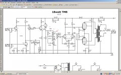
Here are my proposed solutions. With reference to the attached schematic (the problem pot has the arrow), I plan to first replace the 300pf cap (marked 'A') with a 270pf cap. If this does not work, I will replace the 47K resistor (marked 'B') with a 56K resistor. If neither of these options work, I will try both solutions in combination. Failing all of the above, will place a 10-20K resistor at position 'C' in series between the 300pf cap and the pot, as the amp only oscillates when the treble wiper is approaching zero resistance.
What do you guys think? Reasonable approach or should I try something else.
Thanks in advance,
Rob
My newly completed Marshall 18w amplifier is up and running. It's pretty good but I am still troubleshooting one small problem....
The amplifier oscillates on the TMB (treble, mid, bass) channel but only when the treble is turned right up to level 9 or 10. The oscillation begins suddenly and is high frequency. All is fine apart from this. No other settings cause any problems. Before I start pulling parts out, I wanted to run some ideas up the flagpole. The circuit is a variation of the fairly well known Richie TMB.
Here are my proposed solutions. With reference to the attached schematic (the problem pot has the arrow), I plan to first replace the 300pf cap (marked 'A') with a 270pf cap. If this does not work, I will replace the 47K resistor (marked 'B') with a 56K resistor. If neither of these options work, I will try both solutions in combination. Failing all of the above, will place a 10-20K resistor at position 'C' in series between the 300pf cap and the pot, as the amp only oscillates when the treble wiper is approaching zero resistance.
What do you guys think? Reasonable approach or should I try something else.
Thanks in advance,
Rob
Attachments
Hi Rob,
First better say I'm no expert on valve gear, but a couple of thoughts anyway.
I would say you need to determine where the problem is... is it the stage before the pot going unstable, or the stage around V3.
Could it be a "wiring" issue to the pots... stray capacitance etc
My thought would be to try a highish value resistor in series with the grid/s (both) of V3 ???
Also, does the setting of VR7 not have any effect... you imply it doesn't matter where any of the pots are... which seems a bit odd.
Does the oscillation continue with the amp turned down but the treble turned up?
Hi Bigwill and Mooly,
Just tested it - as you both suggest, it is in fact not entirely isolated as I first thought. The oscillation does not occur when the TMB master volume is turned down. In fact, the higher the TMB master volume, the lower the treble has to be turned up to cause oscillation. I missed this first time around due to complaints from the wife about noise - children sleeping, neighbors complaining etc etc. Copped it just then as it whistled away 😀.
Pretty certain it's not just microphony, swapped all tubes around, no change - but will put it on the scope sometime over the WE just to be sure.
Rob
A 'scopes the best way for sure.
Are you sure the wiring is OK... no pickup from other stages or the tranny.
Sometimes it helps to think back to what causes oscillation in the first place... what the conditions are... when the signal feedback (whether stray or by design) becomes positive or "in phase" and when there is sufficient gain in the circuit to overcome the inherent losses of the "network" causing that feedback.
The tone stack is not at fault, no reason to 'fix' it.
Although this is not a high-gain amp, the TMB channel does have anough gain to where problems easily occur if:
-Wire dress is not perfect
-No grid stoppers directly at sockets
-unessesary lead length
-all kinds...
From your schematic I see no grid stoppers! They are a must. Preferably carbon composition, try 10k-68k on 12AX7, and 100-1k on output tubes.
I've had the same problem many times, high frequency oscillation as the treble is upped. Usually wiredress and higher value grid stoppers fix it.
Sometimes a small cap, say 1nF needs to go from plate to cathode (or gnd) to get it stable. Some tweek their amps just that way, even the famous Dumble I've been told.
There is a 470k grid stopper after the volume control but thats the only one..
I suspect it is stray capacitance between wires or the input going too close to the output transformer or speaker.
Get it feeding back and push the wires about with a wooden stick to see what changes it?
I suspect it is stray capacitance between wires or the input going too close to the output transformer or speaker.
Get it feeding back and push the wires about with a wooden stick to see what changes it?
Are u sure that's not just the resistor to the tail of the phase splitter, as shown on the schematic?
Are u sure that's not just the resistor to the tail of the phase splitter, as shown on the schematic?
On the top-left of the schematic, into the triode that drives the cathode follower
Are you using shielded cable from the input connectors to grid, and from one stage to the next?
I've seen ECC83s oscillate when this is not done and interconnect were long enough to pick up noise and feedback. V1a and V1b are prime canidates. V2a to a lesser degree.
I've seen ECC83s oscillate when this is not done and interconnect were long enough to pick up noise and feedback. V1a and V1b are prime canidates. V2a to a lesser degree.
On the top-left of the schematic, into the triode that drives the cathode follower
And that is where a grid stopper is needed the least, (that triode has the least gain of all the gain stages). There's no guaranty, but the first thing I would do is add grid stoppers on all sockets, including on the CF, right on the socket pin.
As you mentioned it may also be wiredress, most likely a combination. Your idea of probing with a wooden stick is sound, but the controls need to be set where it oscillates to have any merit, and I doubt just porking around with a stick will help much. Most important regarding wire dress is tightly twisted and routed non-parallel with offending wires. Cross other wires at right angles where possible, dont run them parallel. Have them run close to chassis, and have chassis grounded at one point only. So many details...
I would install 1K - 4.7K grid stoppers right at the grid pins on every socket with a 12AX7A in it. These will definitely oscillate in a lot of instances with just a couple of inches of lead from an unprotected grid. That 470K resistor after the volume control only performs as a grid stopper if it is very close to the tube in question.
The grid stoppers are sonically transparent, greatly improve stability and quash VHF oscillations that you may not see with your scope. De rigeur on the input stage where they significantly improve resistance to RFI.
Grid stoppers will also often make a less than optimum layout unconditionally stable. (Some of my phono stages would be a good example of that.. 😀 )
You should also install 1K grid stoppers on the power tubes as well.
Grid stoppers may help in case of a ground loop that cause oscillations, but may not.
Check ground wires, somewhere they are cross-wired.
Check ground wires, somewhere they are cross-wired.
The grid stoppers are sonically transparent, greatly improve stability and quash VHF oscillations that you may not see with your scope. De rigeur on the input stage where they significantly improve resistance to RFI.
.
True except for when they become high enough in value as is common in guitar amps. With 20k-and up values they become low pass filters with the tube's input C (which is multiplied by stage's gain). In high gain guitar amps these resistors play an important part in an amp's tone, and we don't want good HF extention in these amps.
Either way, we agree grid stoppers should be included😉
As Wavebourn mentioned obviously a gnd problem may excist, and I've also had such a fault, where either the OPT secondary wasn't grnded or the heater wasn't connected to a fixed point (a positive voltage of course). But I assume this was one of the first things checked🙂
As Wavebourn mentioned obviously a gnd problem may excist, and I've also had such a fault, where either the OPT secondary wasn't grnded or the heater wasn't connected to a fixed point (a positive voltage of course). But I assume this was one of the first things checked🙂
I did not mean obvious things, I meant cross-wired grounds. It is not so trivial, especially in amps with multiple inputs / outputs. I cured several Ampeg SVT amps: that famous bass guitar amps were manufactured with such errors by competent people.
Are you using shielded cable from the input connectors to grid, and from one stage to the next?
I've seen ECC83s oscillate when this is not done and interconnect were long enough to pick up noise and feedback. V1a and V1b are prime canidates. V2a to a lesser degree.
Hi Gimp,
No, have not done this. I will look at rectifying this when I take it apart this WE.
Grid stoppers seem like the go - it is funny but none of the 18w schematics that I can see have grid stoppers including the original Marshall version - does anyone know why this would be?
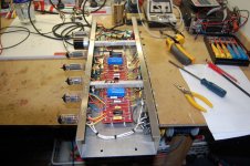
I have included a picture of the inside.
Rob
Attachments
Grid stoppers seem like the go - it is funny but none of the 18w schematics that I can see have grid stoppers including the original Marshall version - does anyone know why this would be?
Anyone knows why. Layout & wiring.
Sorry,
Not to muddy the waters any further but differing from the schematic, I do have grid stoppers on V1 but on none of the other tubes.
Rob
Not to muddy the waters any further but differing from the schematic, I do have grid stoppers on V1 but on none of the other tubes.
Rob
Grid stoppers add losses to oscillating tanks, so ground loops and parasitic capacitive couplings may be forgivable, and don't lead to oscillations.
- Status
- Not open for further replies.
- Home
- Amplifiers
- Tubes / Valves
- Amplifier oscillates - advice sought