hi
Amplifer NPN+PNP Transistors Tester Circuit
When we build our transistor amplifiers, we very often want to use
Complementary NPN + PNP Transistor pairs.
As close matched as possible.
My circuit for this, you can see in Attachment.
A similar circuit should be possible to build.
This one I use for for testing my MultiSim spice models.
--------------------------
About the schematic:
--------------------------------------
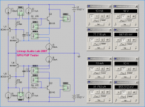
This test shows BD139 / BD140 Testing.
I use 10 Volt C-E. But can be changed, of course.
Also the test CURRENT can be easily changed.
In this case I use 10mA for BD139/140.
- Q1 is transistor under test
- CCS 'I2' 2.11uA, is a compensation for base current in U2.
- CCS 'I3' is where I set test current
- V+ is 10.621V, as 0.621V is compensation for VBE of U2
- The negative PNP side is a mirror of NPN test side
======================================
About my actual test result in the attached picture:
- VBE 0.667 and 0.653 Volt is alright
- Base currents: 77.7uA and 31.7uA is not alright
Because a gain difference hfe=128 and hfe=315 is too much.
So I should not use this pair for any Simulations!
I better try to find a some better matched BD139/BD140 spice models.
Finally ......................................................................
If you setup such a tester circuit, REAL or in your SIM, you may be very surprised!
🙄 Models of NPN+PNP that you have used may turn out to be less good .....
I really recommend you run this test, before you start designing Solid State Amplifiers.
Regards, lineup
Amplifer NPN+PNP Transistors Tester Circuit
When we build our transistor amplifiers, we very often want to use
Complementary NPN + PNP Transistor pairs.
As close matched as possible.
My circuit for this, you can see in Attachment.
A similar circuit should be possible to build.
This one I use for for testing my MultiSim spice models.
--------------------------
About the schematic:
--------------------------------------
This test shows BD139 / BD140 Testing.
I use 10 Volt C-E. But can be changed, of course.
Also the test CURRENT can be easily changed.
In this case I use 10mA for BD139/140.
- Q1 is transistor under test
- CCS 'I2' 2.11uA, is a compensation for base current in U2.
- CCS 'I3' is where I set test current
- V+ is 10.621V, as 0.621V is compensation for VBE of U2
- The negative PNP side is a mirror of NPN test side
======================================
About my actual test result in the attached picture:
- VBE 0.667 and 0.653 Volt is alright
- Base currents: 77.7uA and 31.7uA is not alright
Because a gain difference hfe=128 and hfe=315 is too much.
So I should not use this pair for any Simulations!
I better try to find a some better matched BD139/BD140 spice models.
Finally
......................................................................If you setup such a tester circuit, REAL or in your SIM, you may be very surprised!
🙄 Models of NPN+PNP that you have used may turn out to be less good .....
I really recommend you run this test, before you start designing Solid State Amplifiers.
Regards, lineup
Attachments
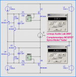
Complementary MOSFET Spice Model Tester
And here is a useful
N-MOS + P-MOS Tester
To checkout that your Spice Models are somewhat correct.
My attachment Tester circuit
shows a test of IRF540N and IRF9540N.
At 1 Ampere and 10 Volt result is:
IRF540 VGS: +3.85V
IRF9540 VGS: -4.34V
Comparing this to figures in datasheet for these MOSFETs
shows that these both models are good!
Regards
lineup
Lineup Audio Lab
Attachments
Thank you for shearing your Mosfet Tester Circuit to this forum.
I already build your Mosfer Tester to test my old Literal Power Mosfet
Hitachi 2SK134 and Hitachi 2SJ49.
However, not more than 2 minutes test both transistor BC550C and BC560C dead
maybe overload or something I do not know.
Please advice how long I should test for Each Mosfet or you have other tips to modified
the Tester.
Your kind attention and advice it highly appreciated.
Regard,
Sunami
Subject : Complementary MOSFET Spice Model Tester
OK, what about R1 change to 220 Ohm and R4 change to 470 ohm.
Any advice...?
Thank you
OK, what about R1 change to 220 Ohm and R4 change to 470 ohm.
Any advice...?
Thank you
- Status
- Not open for further replies.