THD+N 0,5% 100W 8R 10Hz-40kHzApex what kind of figures do you get for this amp ??
THD+N 0,1% 50W 8R 20Hz-20kHz
THD+N 1% 120W 8R 1kHz
Last edited:
Do you have time to sim?I suppose that it works, since apexaudio has a functionnal unit..
Will try some sims of this Vas when i ve some time left, as i ve got
other things to sim currently...
Hi Apex, tonight Ill have some free time and Ill sim the circuit, I suspect this quasy will be better due to it having a EF before the outputs, the first design should really have EF too and I will sim it as such.
Im a bit surprised that your given figures arent better as yamaha have very good figures for this type design.
Im a bit surprised that your given figures arent better as yamaha have very good figures for this type design.
Do you have time to sim?
Apex , the most important is the real world implementation being stable..
As i understand, you have no problems making it work flawlessly,
so sims don t matter no more, but i will do some as soon as possible..
With Darlington outputs have no problems, and I expect better figures with BJT. NMOSFET output is experimental and need to be sim.
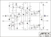
Schematic for experiment with quasy complementary output stage.
Is the amp in post23 the experimental one, or are you using complementary
MOS ?
Many DIYers asking for quasy complementary schematics with IRFP250. This amp is for them. I dont use MOSFETs anymore in my comercial products.Is the amp in post23 the experimental one, or are you using complementary
MOS ?
Many DIYers asking for quasy complementary schematics with IRFP250. This amp is for them. I dont use MOSFETs anymore in my comercial products.
I suppose that the components values are the same than for
the darlington version, at least for the front end..
R16-1kI suppose that the components values are the same than for
the darlington version, at least for the front end..
R20,R21,R22,R23,R24,R25,R27,R28-220R
R26,R29-10R
R30,R31-0R22 5W
R32,R33-4R7 2W
L-1u5H
Z1,Z2-ZF10V
Q11-MJE350
Q12-MJE340
Q15,Q16-IRFP250
A few results.
There s some components values that are inadequate on the schematic,
unless i didn t implement them rightly.
R23/R21 (220R) have a value way too high, increasing the losses such that the
voltage losses of the amp reach 10V per rail.
R23 is useless, and R21 must be reduced to about 10R, but even then, the
hard rail sticking that occur on the negative side is not much reduced.
To get rid of this behaviour, the easier solution is to use a simple transistor
as VAS.
But it s not enough, as the Cgd of the mosfet that are in the negative rail
have a resistor of 220R to discharge them, so the rail sticking still occur unless
the value of this resistor is as low as 20R, which command the use of more rugged
drivers.
All in all, the schematic must be seriously redesigned to work decently.
Using complementary pairs would ease the work.
I ll post later the simulation graphs and the schematic i simmed, for
verifications purposes.
It was stable on resistive load, and also with caps of 100nF
and 1uF paraleled with the load, without LR circuit at the output.
and 1uF paraleled with the load, without LR circuit at the output.
Ill just wait to see your files than, I cant get mine stable, it always has oscilation starting from 500 khz up, which is what I got also when trying to build it a couple of years ago. Im using a EF2 output though on my sims.
A double emitter follower to drive the mosfets?..
Not yet, Im using simple self EF2 BJT stage, no mosfets.
When I do decide to build a amp for listening, then I do employ double emitter folowers to drive mosfets, otherwise I wouldnt use mosfets for outputs at all.
The RC circuit which is in paralel with one side of the current mirror
should be suppressed.
Although the amp become instable without it, it is the source
of a hard rail sticking in the negative going of the signal when
clipping occur...
Anyway, i wont go further in simulations, as it s time consuming,
and the design need a complete rework, sorry for apex...
should be suppressed.
Although the amp become instable without it, it is the source
of a hard rail sticking in the negative going of the signal when
clipping occur...
Anyway, i wont go further in simulations, as it s time consuming,
and the design need a complete rework, sorry for apex...
- Home
- Amplifiers
- Solid State
- Amplifier motherboard