Wow, I have been looking for an amplifier board like this. I have some 500VA 62-0-62V transformers that I would like to use but the rail voltage is a little too high for most other boards using the IRS2092. Rails will be around +/-85VDC - is that too high for the board?
When do you think that you will have the latest version back from production? Are you offering only PCB plus parts list, or also assembled/tested amp board?
When do you think that you will have the latest version back from production? Are you offering only PCB plus parts list, or also assembled/tested amp board?
Last edited:
D
Deleted member 148505
Wow, I have been looking for an amplifier board like this. I have some 500VA 62-0-62V transformers that I would like to use but the rail voltage is a little too high for most other boards using the IRS2092. Rails will be around +/-85VDC - is that too high for the board?
When do you think that you will have the latest version back from production? Are you offering only PCB plus parts list, or also assembled/tested amp board?
Yes, 500VA 62-0-62VAC is ok, but with 1 pair IRFB4227 version (JLAmp1000D) the load should not be less than 4 ohms. +-85VDC Unloaded voltage is ok using your transformer, because I assume it will sag at heavy usage.
Hopefully the PCBs will arrive before October. It will be sold as PCB only, I haven't sourced the parts yet.
For 1 pair version it will be sold as assembled/tested kit.
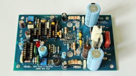
Actually, I am holding out for the 2 pair version, which I think is pictured below. I have a question about it:
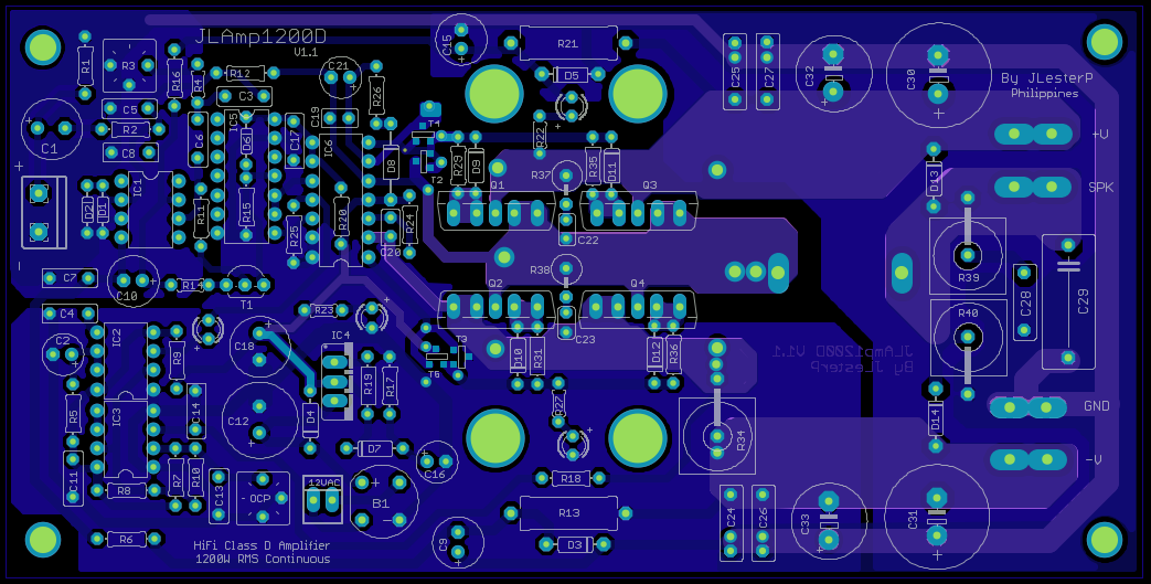
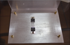
Question: Do the output devices mount below the board (assuming we are looking at the top surface in the image above) and are bent over at 90 degrees and screwed down to a heatsink that everything is mounted on? I assume that is what the four largish holes in the PCB are for - to tighten the screws that fasten the transistors to the heat sink. If this is not correct, then how are the devices mounted to the heat sink?
When you have the PCBs ready, will you also release a BOM for major suppliers in the USA like DigiKey or Mouser? Some of these allow you to upload a spreadsheet BOM and it makes ordering much faster. But this will take some work on your part.
When do you think that you will have one of the new (2 pair) boards built and tested?
-Charlie
D
Deleted member 148505
Question: Do the output devices mount below the board (assuming we are looking at the top surface in the image above) and are bent over at 90 degrees and screwed down to a heatsink that everything is mounted on? I assume that is what the four largish holes in the PCB are for - to tighten the screws that fasten the transistors to the heat sink. If this is not correct, then how are the devices mounted to the heat sink?
When you have the PCBs ready, will you also release a BOM for major suppliers in the USA like DigiKey or Mouser? Some of these allow you to upload a spreadsheet BOM and it makes ordering much faster. But this will take some work on your part.
When do you think that you will have one of the new (2 pair) boards built and tested?
-Charlie
Yes the mosfets will be mounted under the board.
I've created an assembly manual which includes the BOM, the part numbers are specified and it has the product code for RS Components and Element14.
I'll have a built and tested 2 pairs maybe 3 weeks after the PCBs arrived.
Lester
Attachments

Yes the mosfets will be mounted under the board.
I've created an assembly manual which includes the BOM, the part numbers are specified and it has the product code for RS Components and Element14.
I'll have a built and tested 2 pairs maybe 3 weeks after the PCBs arrived.
Lester
Have the boards arrived and have you had a chance to build one up?
I'm still very interested in the new version, if it works as advertised...
D
Deleted member 148505
Have the boards arrived and have you had a chance to build one up?
I'm still very interested in the new version, if it works as advertised...
Didn't arrive yet, there was some problem in shipping according to our middleman. It should have arrived by now if they chose different shipping option.
Yes it will definitely work as advertised 🙂
Have you had a chance to populate and test any of these boards yet?
I'm eager to see some test results on them! 🙂
I'm eager to see some test results on them! 🙂
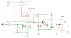
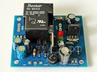
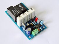
Simple mono speaker protect for my amplifier.
Uses 30A relay.
Hi JPLester,
In this schematic of yours, I see that amp output connector is connected to ground (not speaker) by default via the relay. Is it also true with the actual relay by default, or the opposite?
Could you teach us how this circuit works?
Thanks.
Attachments
D
Deleted member 148505
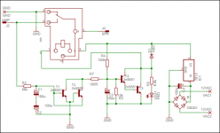
Thanks for pointing out, I mistakenly uploaded the wrong files... here's the correct one.
Simple explanation:
At startup, C3 will charge up.. When it's already charged, T4 and T3 will turn on, thereby turning on the relay. (Turn on delay depends on RC time constant of C3 and R4)
T1 (or T2 if the signal is negative) will turn on depending on the RC time constant of R2, C1, C2.
If T1 or T2 turns on, it shorts the C3 to the ground, thereby turning off the T4 and T3, so the relay will turn off..
Attachments
Last edited by a moderator:
Hello, I want to build this amp (JLAMP1200) for sub application, I´m planning power up it with a smps and 4 ohm load. I understood there is a sigma-delta modulator, wich looks very interesting to me. I´ve looking BOM but I´ve some doubts about replacements:
* for 470 uF 25V cap 105°C LL, part number is UVZ1E471MPD1AA (Nichicon) but RS number is 6841958, this last correspond to Vishay cap rated to 85°C. It´s ok to use cap 85 or 105?
* What´s the difference between IRS2110 and IR2110? I´ve been looking both datasheets and the only difference that I seen is the propagation delay, is like "more simetric" in IRS2011. Can be used IR instead?
Thank you.
D
Deleted member 148505
Hi,Hello, I want to build this amp (JLAMP1200) for sub application, I´m planning power up it with a smps and 4 ohm load. I understood there is a sigma-delta modulator, wich looks very interesting to me. I´ve looking BOM but I´ve some doubts about replacements:
* for 470 uF 25V cap 105°C LL, part number is UVZ1E471MPD1AA (Nichicon) but RS number is 6841958, this last correspond to Vishay cap rated to 85°C. It´s ok to use cap 85 or 105?
* What´s the difference between IRS2110 and IR2110? I´ve been looking both datasheets and the only difference that I seen is the propagation delay, is like "more simetric" in IRS2011. Can be used IR instead?
Thank you.
That capacitor should be a very good one because it is for the supply of the gate driver IC. I chose 105deg C because the capacitor is beside the heatsink of the gate driver regulator. The ambient temp on that area is elevated.
If you can't find 105degC you can use 85degC as long as the capacitor is reliable (> 2000hours at specified temp) based on the datasheet.
As stated in AN-1100, IRS2110 has an internal 20V clamp for each of the supply thereby increases suvivability against transient spikes.
You can also use IR2110, I haven't had any problems with it. I'm using it for almost a year with my JLAmp1000D.
Regards,
Lester
D
Deleted member 148505
Assembling the JLAmp1000D and JLAmp1200D. Once I finished it (it may take a month or so due to my busy sched), I'll post the scope measurements.
Stay tuned 🙂

Stay tuned 🙂
D
Deleted member 148505

Still very interested in these amps... I'm looking forward to your next post.
What kind of testing were you thinking of doing? I think in the past you took some photos of the scope CRT but that was about it. Is there any way that you can do more detailed measurements of frequency response and distortion???
Also, I have a question about how the 1000 versus 1200 handle low impedance (<4R) loads. I need to drive a 2-ohm-nominal load (a subwoofer). I assume that the 1200 with 2 devices per rail would be best suited for this? What rail voltages would you say are "best" for this load?
D
Deleted member 148505
I don't have necessary equipments for testing but, I am planning to setup a THD and frequency response measurement tool using soundcard and PC. I also have to make class D filter for measurement because I don't have AES-17 filter.
My 1000D was already tested to handle 500W into 2 ohms, using 65VDC supplies. I have yet to measure the power output of the 1200D.
These are my recommended transformer rating for my class-d amp. (Linear supply with minimum of 2 x 10000uf capacitors)
JLAmp1000D load : secondary (VAC), current rating (Amperes)
8 ohms load: 55-0-55, 10A
4 ohms load: 50-0-50, 12A
2 ohms load: 45-0-45, 15A
JLAmp1200D
>= 2 ohms load: 55-0-55, 20 A
SMPS: +-75VDC 25A
I think your SMPS recommendation is a little overkill. +/-75V at 25A is 3.75kW of power. 😱 I would think that +/-75V@10A would be enough.
D
Deleted member 148505
That's only my recommendation, I provided a little headroom for it, of course you can also use lower voltages and lower peak power supplies.
Last edited by a moderator:
D
Deleted member 148505
D
Deleted member 148505
I can you please make 2 measurements with the oscilloscope, to make a comparison of forms of waves that do not seem quite right?
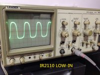
Finished assembling JLAmp1200D, worked at first power up. Here are some scope measurements. The amp is running at 333kHz idle with 4 ohms dummy load connected to it.
Sound is clear, punchy bass, highs are just right and no sibilance. (I'll upload a youtube video lol)
Attachments
-
 jlamp1200d.jpg251.1 KB · Views: 358
 -
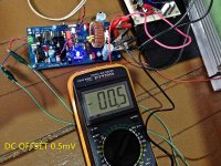 dc offset.jpg384.5 KB · Views: 315
 -
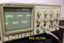 prefilter.jpg250.7 KB · Views: 252
 -
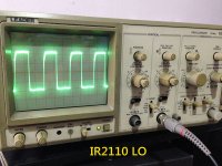 IR2110 LO.jpg288.5 KB · Views: 260
 -
 IR2110 HO.jpg221.3 KB · Views: 583
 -
 cd4069 low out.jpg290 KB · Views: 604
 -
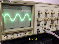 cd4069 hi out.jpg291.2 KB · Views: 632
 -
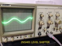 level shift.jpg293 KB · Views: 663
 -
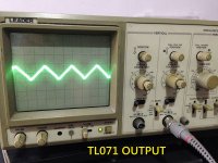 integrator.jpg284.5 KB · Views: 803
 -
 jlamp1000d.jpg313.5 KB · Views: 387
Hi Jlester
greetings just want to ask why IR2110 has heatsink on it try FAN7392 IC
nice boards
warm regards
andrew lebon
greetings just want to ask why IR2110 has heatsink on it try FAN7392 IC
nice boards
warm regards
andrew lebon
- Status
- Not open for further replies.
- Home
- Vendor's Bazaar
- Amplifier Modules and PCBs For Sale