|-
| Name || Lepai T-Amp TA-2020
|-
| Type || Chip
|-
| Application || Small 12W AMP
|-
| Class || D
|-
| Approx Cost || 21€
|-
|
|-
| Designer || L-Pay
|-
| Thread || http://www.diyaudio.com/forums/class-d/90500-lepai-t-amp-ta2020.html
|-
[h=The Project]%1[/h]
[h=Introduction]%2[/h]
The Lepai TA-2020 is a classic ebay china low level amp. But as user Pano said:
"This is about the junkiest built T-Amp I've seen. And the only one with all thru hole components. Real cheap Chinese stuff. The insides are like a bad trip back to the 70s.
But it does sound pretty good! Surprise, surprise."
Over the last 5 years many mods were done to this little amp. So this wiki serves as a repository of information to all those interested in the amp.
[h=Trusted Ebay Sellers]%2[/h]
DIY Audio users have bought from these sellers and they are trustworthy.
[h=Power supply requirements]%2[/h]
From datasheet of TA2020, we can obtain the following values:
- 88%@12W8Ω
- 81%@20W4Ω
- 13.636364W x2 -> 27,26W at 8Ω
- 24.691358W x2 -> 49,38W at 4Ω
Then we need at least a 12v Power Supply Unit and preferably not above 13.5v (because above of that the Lepai zenner diode for protection will reduce it, and will be useless, and some users reported that sound quality decreases). The higher the Voltage supplied, the more power will be able to output the amp, so 13.5V are desirable.
It will also should be capable of at least 3.7A @ 13.5V (13.5 * 3.7 = 50W, which is the needed for 4Ω loads), or 2A @ 13.5V (for 8Ω loads).
For a 12V PSU will need 4.1A @ 12V (12 * 4.1 = 50W, which is the needed for 4Ω loads), or 2.3A @ 12V (for 8Ω loads).
Although the op-amp, and the protection circuit relay also uses power, they values are not significant, and because of the amp would not be always consuming the full power requirements, that values are enough for most of cases
Links of interesting PSU:
- http://www.dealextreme.com/p/12v-3-2a-power-supply-transformer-for-led-light-bulb-ac-110-240v-100394 cheap and adjustable between 11V and 14V
[h=Amplifier Revisions]%2[/h]
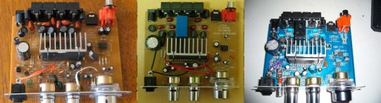
There are at least three revisions of this amplifier the main differences between them are:
- LP-2020 PCB, All through hole components
- LP-2020B PCB, bottom part SMD components, upper part through hole components. Relay for speaker protection
- LP-2020A+ PCB, no bottom side components, upper side both SMD and through hole. Relay protection, and tone bypass switch.
First, second, and third version respectively
[h=Project Modifications]%2[/h]
Do you have some small modifications to suggest for the project that could improve it? Please list them and tell us why they improve the design. If this is discussed in a thread, please link the thread URL here....
[h=Power input related]%3[/h]
[h=Replace the big capacitor]%4[/h]
Can be clearly seen on each version, it's the biggest capacitor present on the left side of the board.
Recommended replacement, the biggest value you can find, at least 4700uF 16V, it's recommended to get a low ERS one. Some people also recommends putting another small capacitor (200nF for example) in parallel, to help filtering the irregularities from power source.
What will improve: general improvement, deeper bass response, and could help with switch-off caused at high volume with low current power sources.
Cost: very cheap, that kind of capacitor will probably cost about 2$.
Difficulty: low, changing the capacitor is easy, there is a lot of space between solder points.
[h=Power source noise filters]%4[/h]
Some power There are a few things that can be done:
- Add a small capacitor as suggested in previous mod.
- Add a ferrite core in the power cord.
- Add more complex filters
What will improve: noise that come from power source, if you have.
Cost: low.
Difficulty: easy.
[h=Inductor remove]%4[/h]
All versions of the Lepai have a small coil after the power socket, some users recommend removing it and simply change it to a solid wire. That's because of its utility is to help filtering power source noise, but it mostly causes a restriction in current that could reach the amplifier.
You could even replace it by another similar 10uH inductor with higher current capability, and you may be able to find a suitable inductor from an old recycled computer motherboard, or else it will cost money better spent on other mods.
Instead of replacing the inductor, it is possible to put a fast soft switch diode in parallel with the factory inductor to bypass "as needed" which is quick and easy, and thereby you get to keep your beneficial filtering except for moments of loud bass (which will turn on that diode rather than allow inductor loss). Dynamic filtering sounds dynamic, so you may or may not prefer that option.
What will improve: Reducing the inductor losses could help to improve sound if your power source is powerful and your amp requires lot of power.
Cost: 0
Difficulty: easy.
TODO:
Power source noise filters, etc.
[h=Sound input related]%3[/h]
Like decoupling capacitors swap, potentiometer, dc offset correction...
[h=Sound output related]%3[/h]
[h=Output Inductors ]%4[/h]
Marked L2, L3, L4, and L5 on the LP-2020A+ PCB.
The output inductors on tripath based amplifiers play a big hole on in the sound quality. Tripath docs and the majority of users here on diyaudio agree that by choosing the right inductors you will certainly improve the sound quality and this may put your tripath based amplifier on another league.
On the Tripath based amplifier produced by lepai it happens that almost any inductor rated 10uH 3.8A is better than the stock ones .
For best results you should look for 10uH inductors that have a low permeability core and can handle atleast 1Mhz. T60-2, T68-2, mpp cores etc.
Some people have reported that wurth XXL work's great for the Tk2050 as you can see here and I see no problems trying those with the TA2020.
Air Cored Inductors
Due to its price and excellent properties, most people prefer Air Cored Inductors over all the above. He go a few tips on the topic:
Best material for air cored inductors/coils ( not taking into account silver, gold etc) :
1- Copper Foil
2- LitzWire
3- Insulated OFC copper wire
4- Standard insulated copper wire
You can buy 0.01mH ( 10uH ) baked multi layer air cored inductors from Jantzen ( EUR 1.65 on ebay ) . The other companies like Solen and Mundorf offer air coils in higher values but you can always unwind non-baked coils to the desired value.
Once you choose the type of material the first thing you wan't to take into account is the cross sectional area of the wire you want to use since going above the wire current capabilities is not an good idea.
Usually the thicker you go the better is the result. But be aware that a single layer conical air cored inductor wound with solid copper or litz wire 23 AWG wound to 10uH will end as a very tall passive component, aprox 60mm tall with an OD of 16 mm.
If you're going for self wound inductors remember to take into account that litz wire is made of multiple individualy insulated strands and follow a little different wire gauge table.
For example:
Litz 23 AWG 100/44 is a wire 22 AWG made from 100 strands of 44 AWG wire.
Also notice that this type of wire is hard to work with while the copper foil is one of the more expensive options but the easier to work with once you know how to do.
To stop the vibrations of the coils you can coat them with varnish.
Air Cored Single Layer Inductor Calculator
Air Cored Multi layer Inductor Calculator
For more info on the output inductors you can refer to tripath ta2020, tk2050, ta2022 technical docs and also do a search on this very forum and you will find alot of info in a much more technical approach .
[h=Tone control related]%3[/h]
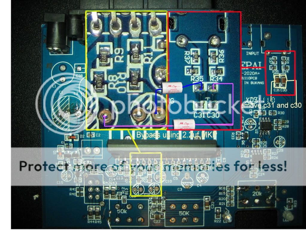
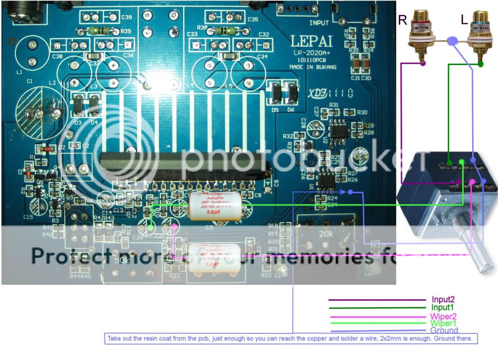
[h=How to bypass tone controls, op-amps and volume potentiometer:]%4[/h]
This mod is that will make you change from "this is a good amp" to " that's alot for $ 15,00".
For V1 check schematics here. Basically you need to replace C4 and C5 with better caps, and if you want to bypass the tone control desolder C2 and C3, and wire to C4 and C5 (don´t know exact which lead needs to be solder, but you should easily follow the traces from the chip).
For V2 check here
For V3 check here, here and here for details on how to bypass everything and how to engage the volume pot again after the op-amps and tone controls and volume pot bypass.
[h=Tone control improvement]%4[/h]
In this post, DrLex suggest other values for components that affect tone control in first revision of the board (Could someone check it for other boards?).
[h=General improvements]%3[/h]
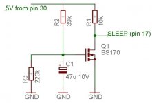
[h=Power on pop suppressor]%4[/h]
One solution is to sleep the amp during power-on using this circuit:
SLEEP pin needs to be isolated as is connected to ground, drilling around with any cutting tool.
What will improve: no power on pop sound, but the amp will take a few seconds to turn on.
Cost: cheap components, about 1$
Difficulty: a little soldering skill needed, medium.
[h=V1 noise from Volume potentiometer remove]%4[/h]
Users report that grounding the case of the volume potentiometer (like could be seen on later revisions of the board) will remove noise that comes from it.
Just solder a wire from any ground point to the metal case of the potentiometer.
Others also do the same with tone control potentiometers, but not sure if its really needed (as their shaft is in contact with metal case that grounds it, not like the volume, that contacts with plastic).
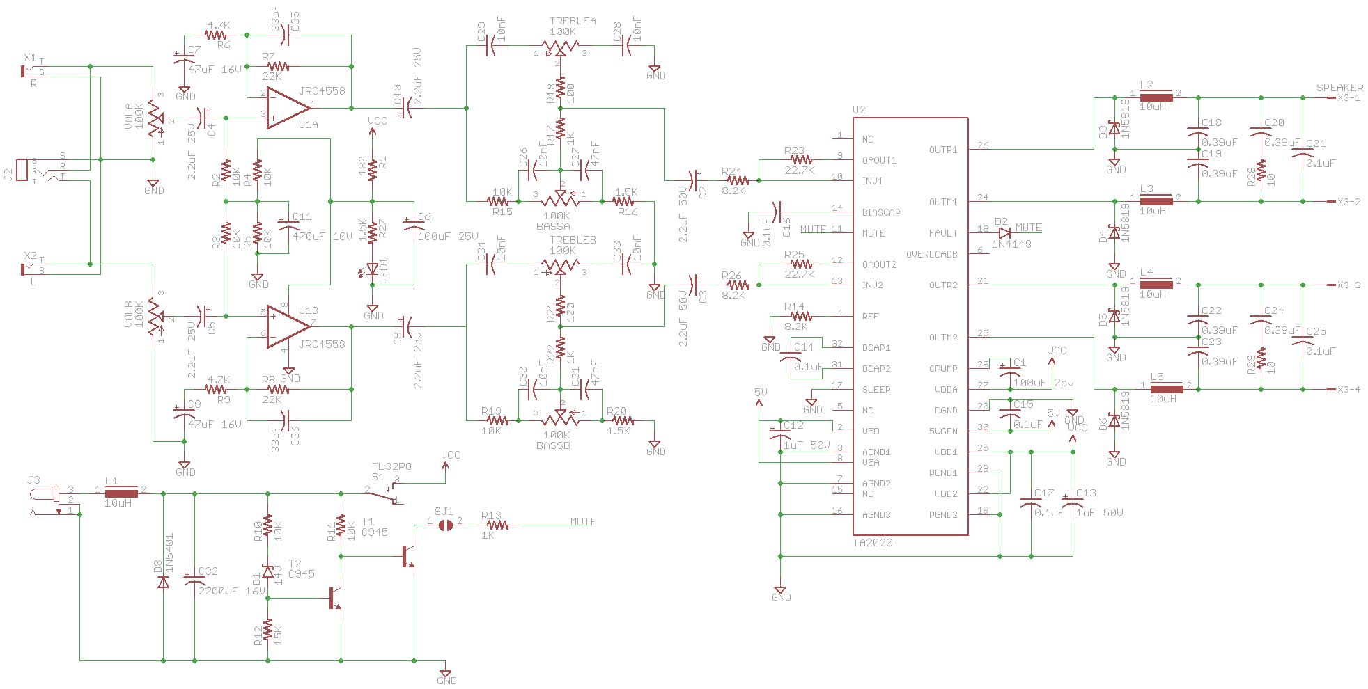
[h=Schematics]%3[/h]
Forum user Danerius provided a schematic for the first revision of the amplifier in the original thread
[h=Stock Photos]%1[/h]
An externally hosted image should be here but it was not working when we last tested it.
Attachments
Will be fine to leave here interesting links to mods before rewriting them to the wiki…
Also will be a good idea to get high quality image of stock PCBs, and remark in them interesting points so we can use one image to explain all the mods.
Also will be a good idea to get high quality image of stock PCBs, and remark in them interesting points so we can use one image to explain all the mods.
djnemesi's hand-drawn schematic of the first version:
http://www.diyaudio.com/forums/class-d/90500-lepai-t-amp-ta2020-45.html#post1875073
DrLex' tone circuit mod:
http://www.diyaudio.com/forums/class-d/90500-lepai-t-amp-ta2020-49.html#post1909096
http://www.diyaudio.com/forums/class-d/90500-lepai-t-amp-ta2020-50.html#post1913535
http://www.diyaudio.com/forums/class-d/90500-lepai-t-amp-ta2020-75.html#post2502471
my own:
http://www.diyaudio.com/forums/class-d/90500-lepai-t-amp-ta2020-60.html#post2258949
including the Eagle CAD schematic:
http://www.diyaudio.com/forums/class-d/90500-lepai-t-amp-ta2020-79.html#post2581971
- Status
- Not open for further replies.