I have been modding a power amp, mostly PS improvements(caps) and signal path resistors.
I decided to argument the power supply lines (lots of shelter in place time). The original supply lines from the main rail caps to the driver/output transistors is a series connected line of parallel runs of 23 gauge wire. There is at least 4 junctions points in the power supply path making the rail feed to the first transistor. I removed those 23 gauge jumpers, replacing them with a larger size wire to transistors. Also, since the supply to the drivers were on the end of this series supply line, I wired a separate supply path to the drivers.
I then tested the amp and there was an nice improvement in detail and dynamics.
While looking over this supply path I discovered that the output layout had additional quirks. Each channel has a push and pull section. The layout was different on each channel. One side had the output transistors in a series chain connection path to the output point like the supply line. That path had the series connection through several single 23 gauge jumper(short) connections. The other channel had (push) 4 output transistors set connected to a single pad, then through a dual 23 gauge jumper. The other 4 transistor (pull) path was a combination series/ parallel paths. All these differences due to a single sided board design limiting connection paths. There are also additional wire jumpers from the diode bridges to main filter capacitors.
So with time and curiosity (limited money investment) I started a major mod effort. I first connected (each channel) all push and pull transistors to the output point in a parallel path connection through bigger solid copper wire. Each transistor had it's own output path.
The sound became very detailed, the increase in bass output easily noticable. The only problem is it lost it's music appeal, at least to me. The top hats shimmered, the bass solid, soundstage better defined. The casualty of this change was the midrange. The overall sound (of my system and to my taste) lost its musicality.
This was a mod step I didn't like overall, and I removed the parallel transistor connection, returned to the original series output connection path but retaining the larger wire( sans the 23 gauge). The musicality return.
I have modded/played with many digital CD/DVD circuits and have a good understanding about the importance of layout in those devices, but amps? That is, discounting size and type of materials, the connection/layout matter more than I thought..... Now that the shimmering top end, solid bass definition is compromised, I feel the loss. Can't I get both that and the musical mids from this amp? Any suggestions. I don't what to wear out the screw mounting holes taking this apart another 10 times.
Would it be possible to get your performance change observations quantified by measurement? "Detail" can be affected by many things, including oscillation issues. It's very difficult to know exactly what's going on without seeing it in numbers, so to speak.
In a power amp, layout is absolutely critical, particularly in the power stage. The output transistors handle large currents, often in excess of several amps during transients. The changing magnetic fields that result from this can affect other parts of the circuit. You want to minimize the loop area.
Also, with large currents being handled, small amounts of DC resistance and inductance have a surprisingly amount of impact. Most importantly, however, stray inductance in the output stage can make the amplifier very unstable.
All of that said, it would be much easier to follow what mods you did if we had images and/or schematics (if there were any schematic changes).
One last thing to consider: Most good power amps have had a lot of time and thought (from very smart engineers!) put into the schematic and board layout. You never mentioned what amplifier you have, but unless I had very good to disagree with the original design, I would leave the layout alone.
This could be an interesting thread but without pictures it's largely wasted. I have absolutely no idea what parallel and series connections are supposed to mean here.
I understand your points, those engineers are very much more in the know than myself. In this case J Curl is the designer, the amp is a Parasound 1500. I didn't change the circuit overall design. But who and how it is constructed is sometimes outside the designer/engineers control. In this case it's a shame the construction in my opinion is not up to it's potential. A 205 watt amp using 23 gauge wiring for both PS and output paths(60amp peak output specs) is weak but doesn't make the design faulty. That being said the design stands on it's own and it's the construction that seems the limiting factor. Thus I tried to improve on the physical/material aspect of the amplifier. But I'm confused about the effects of series vs parallel connection of the output. I agree the magnetics can affect other circuits, and I where the paths crossed, made them 90 degrees. The original layout has the front end off to one side to avoid interaction. The parallel path vs series path doesn't deviate much from each other and follows the same physical path. The series vs parallel path is as discribed, the emitter out is series one to the next emitter to the next to the final emitter, then to the output. That through 23 gauge wire. Parallel means each emitter has a larger wire from each emitter to the output point.
Last edited:
Hard to tell without pictures, but it sounds like you should be prepared for the amp to break out into oscillation at any moment.
Might be a good idea to use a dim bulb tester for that kind of tinkering, and definitely a scope if you have one available.
Might be a good idea to use a dim bulb tester for that kind of tinkering, and definitely a scope if you have one available.
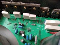
The amp sounds fine in both configuration, just if I could combine the characteristics I like from both would be great. Oscillating usually causes harshness and I don't detect this in either case. However I haven't scoped the output, not thinking it was necessary. The picture shows the parallel 23 gauge daisy chain (I'll called it series) connected PS path of the original construction. The output path from the emitters is also daisy chained, sometimes with only one 23 gauge wire between emitters. My PS mod replaced the pictures 23 gauge wires with large solid core copper wire. All was good. Then in the next mod installed the same large solid copper wire from each emitter to the same original collection point for the output, each with it's own emitter to collection point path( I called it parallel). I didn't like the overall change in musicality. So I restored the original daisy chain path, using the same large wire substituted for the original 23 gauge output wire. The musicality returned, but lost the top hat shimmer and extra firm bass. Now I want them both.
Attachments
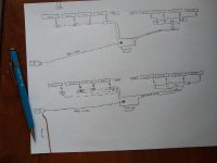
The attached diagram (one channel) is a representative example of my series/parallel mod for discussion. The top diagram illustrates the "series" musical sound wiring vs the bottom diagram representing the "parallel" detailed/firm bass sound. (Jumpers represented by dash lines)
The other channel has both push/pull wiring output paths "series" connected, thus the layout of the left and right channels are not layed out same. I chose this side to also illustrate the different push and pull wiring paths used on the same channel. Let's say one half(left) is daisy chained connected the other parallel connected. The other channel has both push and pull daisy chained.
In the diagram there is the original size jumper wire, and the substituted copper wire. I did scope the output, I detect no oscillation.
Discussion; the sound changes when changing from one, daisy chain, to parallel wiring to the summing point?
Attachments
The resistances of the source resistors swamps the tiny differences in pcb traces layout, so you could also focus on matching those very closely.
Discussion; the sound changes when changing from one, daisy chain, to parallel wiring to the summing point?
So, basically you are comparing a star connection to a bus.
Not surprised they sound different. A star ground is really favourable in a preamp grounding/ps rail distribution but i really have no experience how this concept behaves in a power amp output. Not sure i have even seen this done before.
One factor I haven't mentioned is the rather small board traces carry the output. Some of them have paralleled laid jumpers filled with solder to increase ampacity. So I think both points, star vs bus and/or tiny path impedance seem to make a change. Even at the relatively large signal levels. Think, the far left end transistor output vs the one closest to the summing point. This may be crazy thinking, but how about a signal arrival timing difference between transistor and differing impedances. The ever so slight difference (daisy connection) making for a mid warmth. The "star" making for more concise timing or impedance path equality.
In effect, a slight blurring of the signal?
In effect, a slight blurring of the signal?
Last edited:
One more crazy idea. I haven't confirmed this but the PS path follows a similar daisy chain path and the outboard transistors are on the end of that supply. Marry together, furthest from the PS and furthest from the summing point(?). Highest impedance PS path, highest output impedance path. Each transistor PS/output impedance decreasing as it approaches the summing point
Last edited:
Good thought, I have to check... Because it's a single sided board, to physically determine the where abouts of the connection will require disassembling the amp. Stay tuned!
Last edited:
A quick check shows that the feedback connection for the, will call it the push side is connected after the 4 outputs transistors are summed. However on the pull side the feedback is connected between the junction of the 3 and 4 output transistors. Both channels are done this way.
The attached diagram (one channel) is a representative example of my series/parallel mod for discussion. The top diagram illustrates the "series" musical sound wiring vs the bottom diagram representing the "parallel" detailed/firm bass sound. (Jumpers represented by dash lines)
The other channel has both push/pull wiring output paths "series" connected, thus the layout of the left and right channels are not layed out same. I chose this side to also illustrate the different push and pull wiring paths used on the same channel. Let's say one half(left) is daisy chained connected the other parallel connected. The other channel has both push and pull daisy chained.
In the diagram there is the original size jumper wire, and the substituted copper wire. I did scope the output, I detect no oscillation.
Discussion; the sound changes when changing from one, daisy chain, to parallel wiring to the summing point?
The apparent reason for this is that when all is boiled down complementary transistors are approximations of what is ideal in reality.
With N material in a transistor the carriers are electrons and as charge carriers these are more mobile than holes in P material.
Differences there are between NPN and PNP power transistors will show up with increasing frequency.
How high frequencies are summed in each half prior to merging is my pick for the apparent hierarchy differences in each half of the scheme you have altered.
Sometimes when you see something unusual it can be by design and one should pause to think about it.
Andersonix, great thinking.
Two issues. One, with the top diagram circuit, is the feedback in error because of the connection between 3 and 4?
Second, when I have used a "parallel or star" connection as in the bottom diagram, the feedback from 1 and 2 on the pull side on both channels are lost due to the loss of the connection between 3 and 4. On one channel the the feedback is lost while the other channel retains the feedback from transistor 3. This is because of differing pad connections.
Shouldn't the feedback between transistors 3 and 4 be moved the the summing point? Does the feedback from 4 subtract from 1+2+3.
Last edited:
I'll answer my own question. It's just fine to connect feedback to 3 if you don't break the 3 to 4 connection. I should of been more careful of physical connection and not assume symmetry. So it ends up a typical "simpler" explanation in the end.
Thanks you guys....
Thanks you guys....
- Home
- Amplifiers
- Solid State
- Amplifier layout vs sound