Looks like good explation post 20 .Power supply is on upper part of schematic ,opamp regulated from same +-47v , not the best choice i think . Maybe because of that they needed some kind of compensation via ground .

I still don't see where the +/- 47 V come from.
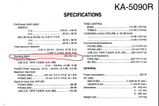
Regarding post 20, I can't read the component values of the MC amplifier, but a typical gain for an MC amplifier would be 10000 times for 20 Hz...50 Hz. That means that the transconductance from the MC input to the current through R205 would be of the order of 10 000/(270 ohm), or almost 40 S, at maximum volume. 1 mohm of common resistance then results in a 4 % error, or about 0.3 dB response error below 50 Hz. If the common resistance is with the other channel, 1 mohm reduces channel separation to 28 dB. The op-amp circuit much improves that by compensating for the current through R205.
Regarding post 20, I can't read the component values of the MC amplifier, but a typical gain for an MC amplifier would be 10000 times for 20 Hz...50 Hz. That means that the transconductance from the MC input to the current through R205 would be of the order of 10 000/(270 ohm), or almost 40 S, at maximum volume. 1 mohm of common resistance then results in a 4 % error, or about 0.3 dB response error below 50 Hz. If the common resistance is with the other channel, 1 mohm reduces channel separation to 28 dB. The op-amp circuit much improves that by compensating for the current through R205.
If they would make separate winding for preamp power supply ,we would not scratch heads ,trying to find explanation . A resistance on the ground path can have effect or not have any effect ,depends on how is everything wired - star ground ,or other ways .But with common power supply for everything ground is complex ,currents flowing everywhere ,and maybe they had no other ways to improve problematic design i think .
IRT compensating for ground currents... Might have a point except that both left and right channels are tied to the same point. Compensation would only be possible if left and right were separated with regard to power paths. Doesn't look like they are. If this indeed is meant to inject current into that ground bus for some form of compensation, I would consider that a 'band-aid' fix - a proper fix would be to beef up the ground structure.
I don't see why that would make any difference. When you compensate for the current that's injected via R205 and do the same for the other channel, shouldn't that just compensate for the crosstalk from R205 and its colleague to wherever they crosstalk to?
Maybe some speaker currents ,ground return ,are in effect ,and more than half of music energy is the same phase in both channels , like bass . So then this compensation kinda of removes effect of bad ground ,which can even make amp oscillate ( i've had that in old design of mine ).
Actually the situation is far worse for loudspeaker return current, about 3828 times worse when the loudspeaker impedance is 8 ohm, and the op-amp circuit doesn't help for that. They must have handled that with some specific grounding strategy. I never realized you can have a transconductance in the kilosiemens range from a MC input to the loudspeaker current...
That 3828 is the ratio of the gain of the main amplifier divided by 8 ohm to 1/270 ohm.
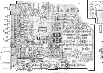
In the schematic of post #8, the rectifier diodes and electrolytics that I overlooked before are in the bottom right corner. The ground wire goes up and then splits into a branch that goes to the loudspeaker outputs and a branch that goes to the rest. I guess that's meant as a star connection to ensure that the loudspeaker return current that flows back to the supply won't go anywhere near the MC input.
That 3828 is the ratio of the gain of the main amplifier divided by 8 ohm to 1/270 ohm.
In the schematic of post #8, the rectifier diodes and electrolytics that I overlooked before are in the bottom right corner. The ground wire goes up and then splits into a branch that goes to the loudspeaker outputs and a branch that goes to the rest. I guess that's meant as a star connection to ensure that the loudspeaker return current that flows back to the supply won't go anywhere near the MC input.
Last edited:
I have the feeling that these op-amps have nothing to do with MC preamp ground, but more with the final stage DC operation and the digital ground which is linked directly to power amp input ground, firstly because of the place where these op-amps are on the PCB inside the power amp and very far from phono preamp and secondly due to R155 and ground work around the power amp input...On the AC side, the op-amps having to drive those output capacitors the op-amps look more like a ground bootstrap for raising the impedance of the power amp input at high frequencies as there's no CCS there.While having this ground linked to the digital ground next after it it's interesting how the ground is routed right at the input of the power amp to create a separation and a high frequency bootstrap to help countering the digital line looks reasonable . Looking at amp's frequency response on all inputs except phono input it starts with 0db at 5 Hz...Not sure how effective would be those op-amps to drive the line input ground on the other side of the PCB so low having the power ground placed physically on the PCB right in the middle without creating a huge hum.Besides the damping factor is really consistent for such an amp at 250 and ground separation between the phono section and power section looks pretty good to me. And to me also at very low frequencies those op-amps still look like an elliptic filter wrapped around the ground itself, but that's highly debatable and maybe unrealistic without solid simulation work... As to MC preamp ground bootstrap my doubts rely more on the fact that kenwood never used something like that in their best integrated amps which were considerably higher power and had daping factors in the order of 15 000...
Attachments
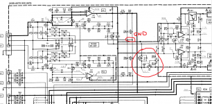
For the compensation to work, the ground connection of R179 should be close to the ground connection of R205 and the ground connection of R180 should be close to the ground connection of R206. It looks like those conditions are met, even though R179's and R180's ground traces make a bit of a detour.
c123/125 which electrically are in parallel with r179 have their own ground path to r205 ground...so maybe there's no dc operation at all...and the way they wrapped that r179 detour around r205 looks more like hum reducing technique than anything else...while c123/125 are just maybe frequency bootstrap or just killing internal oscillations of the whole power amp as someone said before...The more i look, the less i understand...Never the less is quite an interesting topic.
It can be said at the moment that it is not known what this arrangement is for.
A lot of guesswork. I will say a strange situation.
I have to admit that "It's a Quirk" is interesting. in fact the function of this something might lead the amplifier measurements with and without this IC .... maybe ... as long as the measurements show something.
A lot of guesswork. I will say a strange situation.
I have to admit that "It's a Quirk" is interesting. in fact the function of this something might lead the amplifier measurements with and without this IC .... maybe ... as long as the measurements show something.
If you have this amp is quite simple to get an ideea what it is for...just simply remove one op-amp from one channel and see the difference.
If you do, measure from the MC input to the loudspeaker output at maximum volume and check the frequency response, left to right and right to left crosstalk.
I think it's clear that the op-amps cancel the ground current from the feedback networks, but the question remains, why? It seems as though the input ground and output grounds are not wired separately as they should be? I suspect that the effect of removing these op-amps would be subtle, unless you knew exactly what to look for.
- Home
- Amplifiers
- Solid State
- amplifier KA-5090R - strange circuit in the Kenwood KA-5090R amplifier - Repair