I'm repairing Kenwood KA-5090R
It has on one DC channel at the output ...
Interestingly, it seems that the transistors in the OK and DC path are at the output - a topic for further analysis
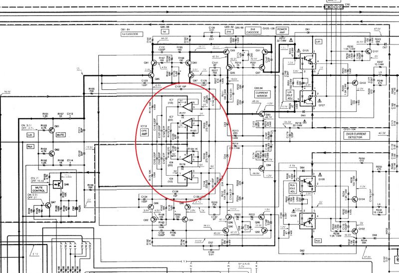
But this is still a small problem, because there are two operational amplifiers IC7 and IC8 in the feedback circuit.
But the circuit is strange, the amp outputs are (cascaded) shorted to ground! What is this amp supposed to do? linearize gain? but how?
I don't get it .... 😱
Anyone seen something like this? 😛
It has on one DC channel at the output ...
Interestingly, it seems that the transistors in the OK and DC path are at the output - a topic for further analysis
But this is still a small problem, because there are two operational amplifiers IC7 and IC8 in the feedback circuit.
But the circuit is strange, the amp outputs are (cascaded) shorted to ground! What is this amp supposed to do? linearize gain? but how?
I don't get it .... 😱
Anyone seen something like this? 😛
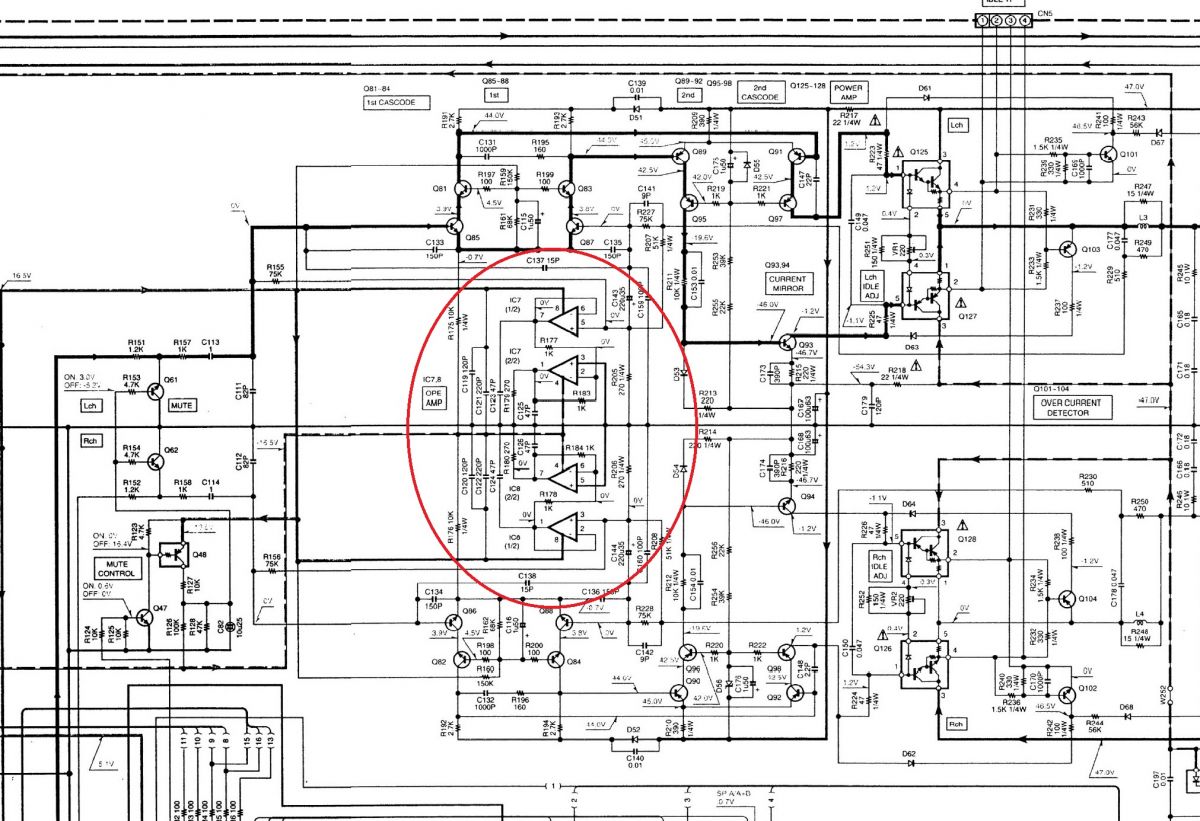
R179 compensates for the current that R205 injects into the centre line, which I presume to be ground, but I haven't a clue why it needs to be compensated for.
Is the line in the middle indeed ground and is the power supply a standard symmetrical supply or something with a resistive divider or op-amp producing the ground potential?
Does anyone have a clue what R207 is for?
Is the line in the middle indeed ground and is the power supply a standard symmetrical supply or something with a resistive divider or op-amp producing the ground potential?
Does anyone have a clue what R207 is for?
Hi .I see one possibility ,its like overload / limiter function . Opamps are loaded 270ohms , which may draw significant current on high signal peaks ,thus sagging +16.3v line . R159 getting voltage from that line ,may be affected if voltage will drop .From picture is not clear , where +16.3v comes from ,how good is it regulated . Maybe it will affect mute .
Looks like there are many circuits powered from +16.5V ... Really strange function . Does pcb match schematic ?
1. There is no virtual GND here.
2. 270 Ohm on the output of the amplifier is probably not enough to burden the power supply so that it drops?
2. 270 Ohm on the output of the amplifier is probably not enough to burden the power supply so that it drops?
Theoretically it can be more than 50ma ,if this voltage is simply zener regulated ,it may drop from such load .About pcb i mean matching in real device ,if you repairing it ,you can check that .Sometimes schematic have errors .
Voltage divider is interesting too . 51k/270 ohms ,with +-47V power supply voltage it gives only 247mv . But a feedback capacitor C143 is connected there. This sets AC gain ,DC gain is 1 . But opamp from this schematic can only modulate power supply a bit ,nothing more . Also strange - opamps outputs loaded by capacitors ,most opams don't like capacitors at output .
No virtual ground, that 'central line' is tied to chassis. All the 'grounds' on the schematic are chassis grounds. R205/R207 set the closed loop gain (AC coupled via C143) with some ultrasonic compensation by C141/R227. +/-16.5 volt lines are tightly regulated, the op-amp current draw is not going to cause them to sag.
There are new ideas ... that it works in a comparator "system" ... We'll see if the author of this idea explains how it is supposed to work ...
R205 is 'low' when compared to R155 and R207, and can be considered a near virtual ground. IC7 pin 5 (+) sees the sum of the amplifier output and the amplifier input (through R155 & R207). IC7 (1/2) is simply a voltage follower, so the output is the same as the input. The output of IC7 (1/2) goes to IC7 (2/2) which is an amplifier with a gain of -1. The output of (2/2) just goes to ground through a 270 ohm resistor. Considering the impedances in that circuit, those pf caps can't be anything other than HF noise suppression. I see no function of this group of parts......
Maybe its supposed to inject some current into ground ,to reduce ground loop or something like .
For a given value of R205 and a given desired cut-off frequency, you need less capacitance for C143 with than without R207. No idea about the other stuff.
What does the power supply schematic look like?
What does the power supply schematic look like?
Suppose you play a record at a high volume using an MC cartridge. A few milliohms of common ground resistance between the MC input and R205 is then enough to mess up the low-frequency part of the frequency response, and to mess up the channel separation. The op-amps will largely correct that.
- Home
- Amplifiers
- Solid State
- amplifier KA-5090R - strange circuit in the Kenwood KA-5090R amplifier - Repair