Hi all
Any body can comment on several design knack as attached schematic ?
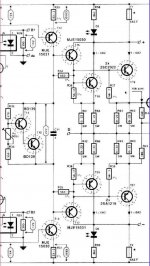
1.What is the purpose of R34 which is 562 ohm resistor connected between B and E of driver stage transistor ?
2.What is the purpose of R36 and R37 which are 56.2 ohm resistors connected between B and E of output state transistors ?
3.How to determine these two resistor value properly ?
Appreciated for any input.
ward
Any body can comment on several design knack as attached schematic ?
1.What is the purpose of R34 which is 562 ohm resistor connected between B and E of driver stage transistor ?
2.What is the purpose of R36 and R37 which are 56.2 ohm resistors connected between B and E of output state transistors ?
3.How to determine these two resistor value properly ?
Appreciated for any input.
ward
Attachments
I recognize the schematic, as from an Elektor Amplifier.ward said:Hi all
Any body can comment on several design knack as attached schematic ?
1.What is the purpose of R34 which is 562 ohm resistor connected between B and E of driver stage transistor ?
2.What is the purpose of R36 and R37 which are 56.2 ohm resistors connected between B and E of output state transistors ?
3.How to determine these two resistor value properly ?
Appreciated for any input.
ward
It is a way to direct some current running.
It will run like I=0.650V/R, through those resistors.
But why?
I think someone else have to answer.
Think reasons can be more than one.
Anyway those resistor raise the current in driver transistors
to more than what is needed to drive the output transistors.
And that can make the drivers operate better - more linear.
/halo - interested to read the answers
halo & wardward said:Hi all
Any body can comment on several design knack as attached schematic ?
1.What is the purpose of R34 which is 562 ohm resistor connected between B and E of driver stage transistor ?
2.What is the purpose of R36 and R37 which are 56.2 ohm resistors connected between B and E of output state transistors ?
3.How to determine these two resistor value properly ?
is still waiting for the correct answer
from the "amplifier expert panel" 😀
-------------------------------
Maybe jcarr and the others are just out for lunch
/halo - eats his lunch alone at home
Elektor / Elektuur
Yep, I see some TUN's, TUP's, and maybe a DUG.
Live was so much simpler than.
I loved to get those juli/august numbers with over a hundred things to do with a soldering iron. Lots of (crappy) electronic potentiometers.
Yep, I see some TUN's, TUP's, and maybe a DUG.
Live was so much simpler than.
I loved to get those juli/august numbers with over a hundred things to do with a soldering iron. Lots of (crappy) electronic potentiometers.
Re: Elektor / Elektuur
And you could learn about them.
now, Elektor, I am sorry to say,
have almost only digital circuits, microprocessors and PC-crap
and the audio is mostly IC-based.
Every now and then, there is is a Tube design
but it is very long between the good audio-stuff, nowadays
Even longer time between the interesting discrete designs
/halo - things ain't what they used to be
- and will probably never be ....... 😉
Those old years of edition had really something on transistors.ststone said:Yep, I see some TUN's, TUP's, and maybe a DUG.
Live was so much simpler than.
I loved to get those juli/august numbers with over a hundred things to do with a soldering iron. Lots of (crappy) electronic potentiometers.
And you could learn about them.
now, Elektor, I am sorry to say,
have almost only digital circuits, microprocessors and PC-crap
and the audio is mostly IC-based.
Every now and then, there is is a Tube design
but it is very long between the good audio-stuff, nowadays
Even longer time between the interesting discrete designs
/halo - things ain't what they used to be
- and will probably never be ....... 😉
These resistors are for reducing current gain (make it more predictable), increase the linearity also (I suspect) and also speed up turn off time.
The values of these resistors are like those for gates in mosfet amps, not so critical, certianly not E196 values!
The values of these resistors are like those for gates in mosfet amps, not so critical, certianly not E196 values!
Hi,
1 and 2 and this is with a huge IIRC (If I Remember Correctly) help overload recovery by draining away the saturation charge in the PN Junctions of the Output/Driver Transistors.
I doo seem to remember references to this even in Douglas Selfs stuff, but may be mistaken. So don't quote me on any of this....
Sayonara
1.What is the purpose of R34 which is 562 ohm resistor connected between B and E of driver stage transistor ?
2.What is the purpose of R36 and R37 which are 56.2 ohm resistors connected between B and E of output state transistors ?
3.How to determine these two resistor value properly ?
1 and 2 and this is with a huge IIRC (If I Remember Correctly) help overload recovery by draining away the saturation charge in the PN Junctions of the Output/Driver Transistors.
I doo seem to remember references to this even in Douglas Selfs stuff, but may be mistaken. So don't quote me on any of this....
Sayonara
Re: Re: Amplifier design knack ???
you can find similar discovery.
In Self site I think it was in the output stage.
-------------
Rod Elliot had a discovery when he tested how to design
the DOZ amplifier.
The Distortion changed when he attched
that b-e resistor to the vas-transistor in DOZ.
I will go search the ESP-article/project.
-----------------------------------------------
Death of Zen A new Class-A power amplifier
http://sound.westhost.com/project36.htm
Elliot say in comment to Figure 3. A test setup:
/halo
Yes, both in Self site and Elliot sites,Kuei Yang Wang said:Hi,
1 and 2 and this is with a huge IIRC (If I Remember Correctly) help overload recovery by draining away the saturation charge in the PN Junctions of the Output/Driver Transistors.
I doo seem to remember references to this even in Douglas Selfs stuff, but may be mistaken. So don't quote me on any of this....
Sayonara
you can find similar discovery.
In Self site I think it was in the output stage.
-------------
Rod Elliot had a discovery when he tested how to design
the DOZ amplifier.
The Distortion changed when he attched
that b-e resistor to the vas-transistor in DOZ.
I will go search the ESP-article/project.
-----------------------------------------------
Death of Zen A new Class-A power amplifier
http://sound.westhost.com/project36.htm
Elliot say in comment to Figure 3. A test setup:
Some interesting things came to light during testing, especially when I included the resistor (R6) from base to earth on Q2. With no resistor, I measured a distortion of 0.15%, and this was almost completely 2nd harmonic. There was a very noticeable degradation of the positive going slope on a 10kHz square wave, and a fairly low slew rate resulted. Adding the resistor improved this dramatically, and reduced the distortion to 0.05% - but it was now almost completely 3rd harmonic.
This will create a conundrum for some - would you rather have very low levels of 3rd harmonic distortion, or considerably larger amounts of 2nd harmonics (bearing in mind that the 3rd harmonics are still there). I cannot see any good reason to tolerate any more distortion than is absolutely necessary, so considering the much better slew rate (and therefore high frequency performance), I will be including this in the final design. You might want to leave it out if you want the 2nd harmonics, but I don't think the end result will be very satisfactory.
This is due to the transistor's turn-on and turn-off characteristics becoming more symmetrical by providing a base discharge path, but I did not expect such a large difference. The frequency response extends to over 100kHz at full power (6V RMS for these tests), and square wave response shows that the amp is both fast and stable - and this with a very ordinary switching darlington. I saw no evidence of measurable distortion above the 3rd - there must be some, but I have no way of measuring it. The 3rd harmonic appears to be an almost perfect sine wave, with some very small variations.
/halo
Re: Re: Amplifier design knack ???
Halo, do you have a job to go to, or do you just sit at home all day posting prosaic observations to diyaudio?halojoy said:/halo - eats his lunch alone at home

Re: Re: Re: Amplifier design knack ???
halojoy said:
Yes, both in Self site and Elliot sites,
you can find similar discovery.
In Self site I think it was in the output stage.
-------------
Rod Elliot had a discovery when he tested how to design
the DOZ amplifier.
The Distortion changed when he attched
that b-e resistor to the vas-transistor in DOZ.
I will go search the ESP-article/project.
-----------------------------------------------
Quote from [Elliott Sound Products] -- Power Amplifier Design Guidelines
http://sound.westhost.com/amp_design.htm#op_stage
But I am still confused with how does it work ?
look forward to your comment !!!
ward
Stick a little to these resistors please
I think peranders and Kuei have given the hints.
Those resistors in darlington stages
are benefitial in several ways.
It serves among other funtions, to discharge
the base of transistor, when it is turned off.
I think we have covered the most of this.
/halo
I think peranders and Kuei have given the hints.
Those resistors in darlington stages
are benefitial in several ways.
It serves among other funtions, to discharge
the base of transistor, when it is turned off.
I think we have covered the most of this.
/halo
knack
IIRC Elektor (or Elektuur as it is called in Holland) also advocated this as a means to have the driver stages running in Class A. That way they could run the output stage close to class B because the drivers actually contributed to the output at low levels, in addition to driving the output stage.
Jan Didden
biased opinion
It isn't always necessary to find complicated answers to things in audio design. In my experience it is being able to see the wood from the trees that really helps and this usually leads to a reassuringly simple understanding of what is going on.
IMO R36-R39 are simply there to bias the drivers to a more linear operating point. Their bias current will be 0.7/R36x2 plus the base currents of the output transistors. Normally, the resistor bias is set to swamp the base current at zero output voltage. If the drivers are not biased in this way their Ic will be equal to the output transistors Ib and the latter is extremely non-linear near the cross-over point. IME it is best to keep as many transistors as linear as possible - we conceed class (A)B for the final output transistors as a practicallity, for efficiency.
The purpose of R34 and R35 is not obvious to me. In many designs I've seen resistors are not used like this because they load the voltage gain stage. The only time I've seen anything similar is when a resistor is connected between driver input and amp output. I am inclined to think R34 and R35 may have been added optimistically.
I read Rod Elliots article (thanks Ward) and I agree that it does not explain R34/R35. I think Rod's article is very interesting and I salute him for having read the ARRL handbook (highly recommended for fundamental stuff). I'm pleased he's noticed that emitter followers can become unstable in certain loads. I wasn't sure about his conclusions when he used a LC load as a load and then showed oscillation on a scope: you always get oscillation with a pure LC load - because it is a resonator. So It isn't clear to me what he was looking at. He advocates an output L with parallel damping resistor for all designs; this is a fair precaution but is not necessary with all designs.
Hi Trader,
your UN flag is still gone 🙁
I agree that R34/35 serve no really good purpose. In theory, they do not load the VAS because the emitters follow the bases AC-wise. However, they don't do so ideally, and the VAS gets a dynamic load that is governed by the nonlinearity of the driver BE junction.
Bias for the drivers in this example here is 0.7 V/27R = 26 mA. This is about as much bias as some manufacturers allow the output transistors to have.
Still, it is not ideal to connect R36 etc. to either output or output transistor emitters. At some point, one driver gets switched off as the bias in the other one increases because there is only a fixed bias voltage for the drivers.
It is much more efficient to connect the driver emitters through a single emitter resistor that does not have any connection to the output. I think D. Self suggests something to this effect, too.
Regards,
Eric
Re: biased opinion
Hi Traderbam,
It was not my intention to come up with a complicated guess. I know for sure that Elektor had designs doing what I said: heavily bias the driver stages with a low resistance path to the speaker, so they will provide the low-level part of the output with the output stage almost completely in class B. That way the drivers "fill-in" the missing xover part. This design seems to be one of those; it would explain the low resistor values.
Are you familiar with "occam's razor", stating that the simplest explanation which doesn't require an esoteric theory is most probably the right one? 😉
Jan Didden
traderbam said:It isn't always necessary to find complicated answers to things in audio design. In my experience it is being able to see the wood from the trees that really helps and this usually leads to a reassuringly simple understanding of what is going on.
IMO R36-R39 are simply there to bias the drivers to a more linear operating point. Their bias current will be 0.7/R36x2 plus the base currents of the output transistors. Normally, the resistor bias is set to swamp the base current at zero output voltage. If the drivers are not biased in this way their Ic will be equal to the output transistors Ib and the latter is extremely non-linear near the cross-over point. IME it is best to keep as many transistors as linear as possible - we conceed class (A)B for the final output transistors as a practicallity, for efficiency.
The purpose of R34 and R35 is not obvious to me. In many designs I've seen resistors are not used like this because they load the voltage gain stage. The only time I've seen anything similar is when a resistor is connected between driver input and amp output. I am inclined to think R34 and R35 may have been added optimistically.
I read Rod Elliots article (thanks Ward) and I agree that it does not explain R34/R35. I think Rod's article is very interesting and I salute him for having read the ARRL handbook (highly recommended for fundamental stuff). I'm pleased he's noticed that emitter followers can become unstable in certain loads. I wasn't sure about his conclusions when he used a LC load as a load and then showed oscillation on a scope: you always get oscillation with a pure LC load - because it is a resonator. So It isn't clear to me what he was looking at. He advocates an output L with parallel damping resistor for all designs; this is a fair precaution but is not necessary with all designs.
Hi Traderbam,
It was not my intention to come up with a complicated guess. I know for sure that Elektor had designs doing what I said: heavily bias the driver stages with a low resistance path to the speaker, so they will provide the low-level part of the output with the output stage almost completely in class B. That way the drivers "fill-in" the missing xover part. This design seems to be one of those; it would explain the low resistor values.
Are you familiar with "occam's razor", stating that the simplest explanation which doesn't require an esoteric theory is most probably the right one? 😉
Jan Didden
sharp thinking
Hi Jan,
I agree with Occam. Makes my eyes water for some reason!
I understand what you are pointing out: that if the output transistors are "off" then the drivers will be driving the load through R36etc, but in my opinion this is not what they are for, as their values are so high that very little current will flow to the load this way. Generally, the output transistors are biased so that they are never both completely off at the same time. I suppose the drivers driving the load directly is more likely to be effective in the CFB configuration.
Just my opinion.
BAM
Capslock,
Flagless indeed! I may have to find a UN flag picture and attach it to my ID (how do people do this?).
"Still, it is not ideal to connect R36 etc. to either output or output transistor emitters. At some point, one driver gets switched off as the bias in the other one increases because there is only a fixed bias voltage for the drivers."
Yes and no. True, eventually with enough current drawn even the driver bias will be depleted. But perhaps this is not so important at the point where the other half is firmly in control of the output. I think this is most curcial near the cross-over where both halves are equally contributing to distortion. The thing I don't like about the bias spanning across driver emitters is that the two halves are no longer electrically independent. That matters if you want to keep the Vbe changes of the 'off' side from affecting the current in the 'on' side and if you want to match the two sides from driver to output rather than trying to match both drivers and both power transistors. Especially in the case of a pseudo-complementary output stage this is not possible or desirable.
I think most of can agree that this resistors do have a purpose. Compare all darlingtons and huge "tripletons". Everyone almost have these resistors.
In class A and B, increase linearity and speed
In class D, decrease switch off time.
Those resistors aren't for fun. Semiconductor manufactures don't do anything for fun. It must serve a purpose.
In class A and B, increase linearity and speed
In class D, decrease switch off time.
Those resistors aren't for fun. Semiconductor manufactures don't do anything for fun. It must serve a purpose.
- Status
- Not open for further replies.
- Home
- Amplifiers
- Solid State
- Amplifier design knack ???