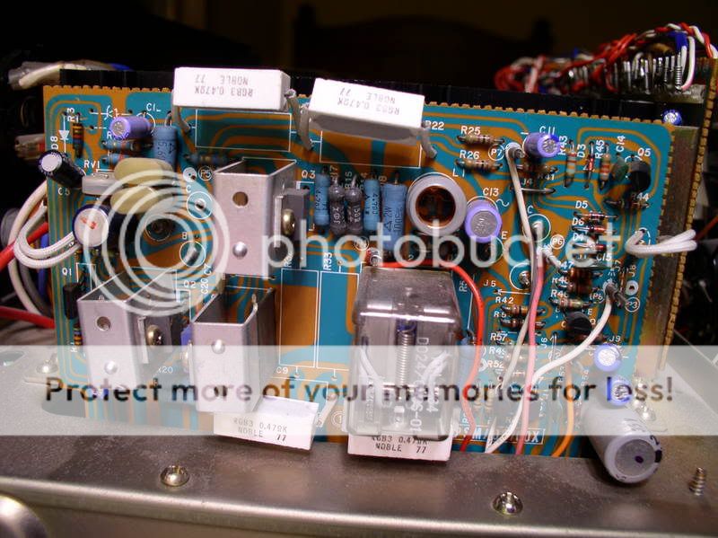
here are some pics of the boards: the first two pics are of the protection circuit/relay board. in the upper left of the first one is a single pot, you can also see a top view of this pot in the second pic.
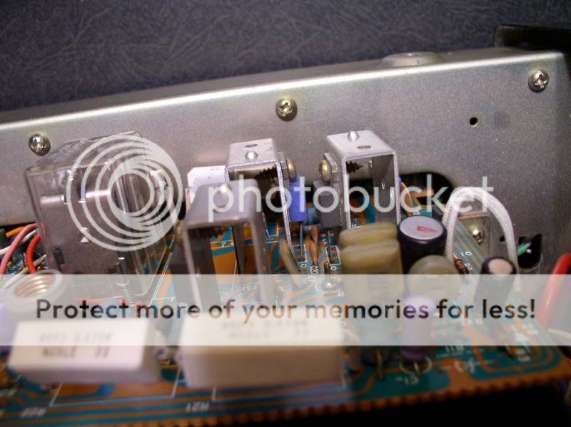
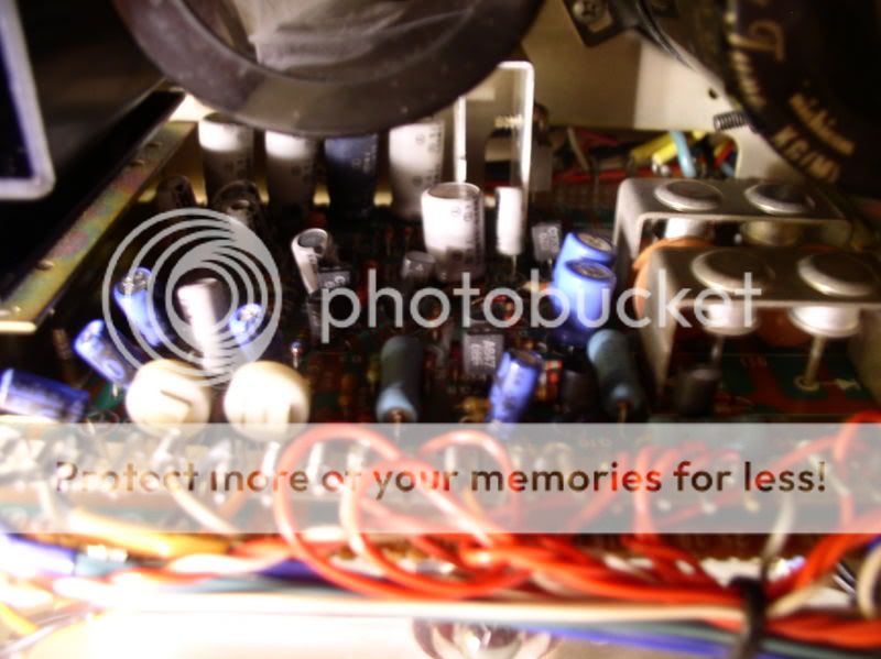
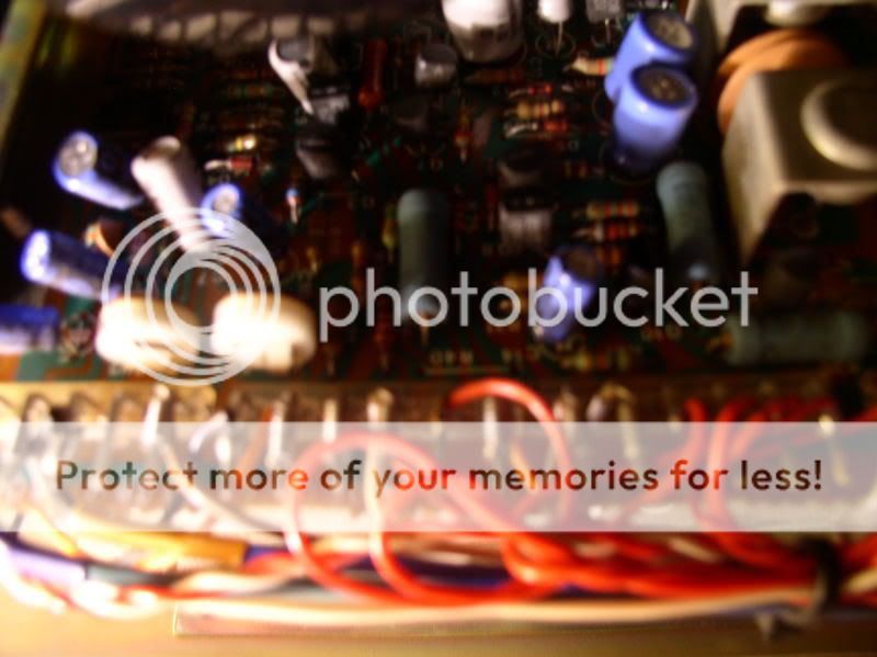
the two below are of the board parallel to the faceplate. on the left are two pots right next to each other--I think they are the bias and offset ones, but I don't know for sure. sorry, these pics are not very good--it was very hard to get the camera in to take them. If it is absolutely necessary, I can do some disassembling and get a better closeup.
Glenn--let me know what you think I should do next.
thanks!!
Henry
It looks like the two transistors by the relay are for the relay. The three caps in the lower right corner look like the ones for the relay circuit. Two white sleeved leads on right look like over-heat shut-down.
The right middle transistor, right top transistor (Q5). and D3,4,5,6 are foldback current limiting.
Q3 is the NPN driver, the blue one is the PNP driver. Q2 is the Vas, it has a bootstrap cap. Q1 is a dual transistor, I see no DC off-set control. RV1 looks like bias, there is probably a STV4H on the heatsink (two white sleeved leads next to bootstrap cap).
The pots behind the front panel are probably for the meters.
djk:
wow, I find it incredible that you know all that from a single pic and no service manual!!!
what do I replace besides the caps? which transistors/diodes could be bad or suspect?
I see no gassing or bad signs on anything.
How can an amplifier not have a DC-offset pot??? the offset on it is ~35mv/channel, and the offset on my "working" BS-5500 is ~50mv/channel. how do you set this???
btw--what are those two white-yellow oval things on the left of Q3? I noticed that each of them has to wires sticking out, and they are connected together in series, if you know what I am
trying to say.
something else you might want to know--the output transistors are soldered directly to the relay board, so they will have to be unsoldered to recap and fix the amp. You can see where two are connected--one is just under and to the right of C13, and the other is to the left of Q3, under those oval things. You cannot see the last two, they are connecterd to the very bottom of the board.
thanks!!!!!!!!
Henry
Hey Henry,
I don't post here often but I took one look and saw what looked much like my old Sansui amp. Yep, you got an old one allright! The rest are absolutely correct about changing all of the small bypass caps. Even if there isn't evidence of drainage, they tend to dry up, especially if near a heat sink. This changes voltages and filtering charistics. Caps in old TV's do the same... The two things (oval) are foil caps with polystyrene dielectric, most likely. eg 223, 22000pf... 2R2, 2.2pf... I have seen those type used for anti-oscillation and high frequency filtering. Even if you replace all of the caps, you may want to consider putting a scope across the output, and see if your amp is oscillating. The fact that it gets warm and acts up says it is a cap by a heat sink, wether big or small. If you put new caps throughout, and there is no oscillation, AND it is still acting up, I'd start with replacing semiconductors, starting with the diff pair. By the way, I have seen many amps without variable offset. This amp isn't so very different than other commercial amps. Look at other schematics and see where the majority put their bias transistors and bias pots. Relate that to your output transistors, and you should quickly be able to tell where your bias pot is. Yes, I agree with DJK. The 2 pots behind the front pannel are probably for calibration of the meters. Remember, your amp is not too different than most commercial amps of the time, so don't fret too much about the manual. You can fix it!!! I can't tell you how many amps I fixed without a manual. Sometimes you have no choice, like this case. There's no shame in shotgunning in these cases! Looks like a real peach of an amp. Watch out when soldering and de-soldering. Those old boards love to delaminate!!!!! OK, enough of my babbling already. Hope this helps....
Otter
Hi Henry
I'm a new comer in this forum having recently bought an Setton RS-660. Unfortunately this gorgeous unit has some little problems. This is why I was searching internet about this model and finally found this forum. Having read your post saying that "the reason this matters is that I have access to an RS-660 service manual" I suddenly realized that you may save my life, well my RS-660's life!
Please would it be possible to get a copy (either by scan or xerox copy) of this service manual? Indeed I will pay for the delivery fees if you decide to send it by postmail. I do have the service manual for the Setton AS-3300 (and the amplifier as well) and will send you the scans if you are interested in.
I really hope that this will be possible for you.
All the best
Thierry
Hi again Henry
I forgot to mention that both a Setton BS-5500 and a RS-5500 have been sold on ebay last august in france. The ebayer who won (emorejeves) maybe could help you.
Best regards
Thierry
I forgot to mention that both a Setton BS-5500 and a RS-5500 have been sold on ebay last august in france. The ebayer who won (emorejeves) maybe could help you.
Best regards
Thierry
Hello,
May be it's late, but some Setton manuals are here:
- Owners/Service Manuals
Regards.
Alain, from France;
May be it's late, but some Setton manuals are here:
- Owners/Service Manuals
Regards.
Alain, from France;
- Status
- Not open for further replies.
- Home
- Amplifiers
- Solid State
- amplifier clicking in and out of protection