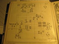
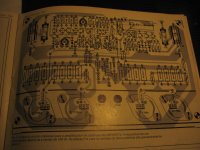
Here is a Hitachi lateral mosfet amplifier circuit.
I took this and added numerous improvements for myself.
I added decoupling of front end from output stage.
I changed front end transistors to mpsa42/92.
If you cant find mosfets for it I used ALF16N16W and ALF16P16W lateral mosfets.
I took this and added numerous improvements for myself.
I added decoupling of front end from output stage.
I changed front end transistors to mpsa42/92.
If you cant find mosfets for it I used ALF16N16W and ALF16P16W lateral mosfets.
An externally hosted image should be here but it was not working when we last tested it.
Last edited:
Hello Nigel, thank you for the information, unfortunately this is not the article I was looking for the one I wanted either used 8 Toshiba Mosfets and the other one used Siemins BUZ musfets, but I will try this one anyway, thanks once again Pepe
I recall the Crescendo and Mini Crescendo amplifiers using 2SK135/2SJ50 pairs
I have build the Mini version and etched my own pcb during those years for my guitar combo amp. Worked very well...
I still have the PCB and the ILP HY-83 preamp module. the amp cab was destroyed
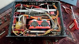
I just bought a buzamp from Germany.
It looks like **** inside, even if parts are of good quality. Someone really likes paint")
I fixed some bad contacts and would like to adjust BIAS, trimmers were firmly glued and difficult to replace, but my questios is, what is proper BIAS?
One channel was about 80mA and the other about 8mA
I would have thought 100-200mA is good?
Supply is 2x55VDC and there is a big enough heat sink.
It looks like **** inside, even if parts are of good quality. Someone really likes paint
I fixed some bad contacts and would like to adjust BIAS, trimmers were firmly glued and difficult to replace, but my questios is, what is proper BIAS?
One channel was about 80mA and the other about 8mA
I would have thought 100-200mA is good?
Supply is 2x55VDC and there is a big enough heat sink.
Attachments
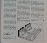
http://www.designfactory.co.za/audio/Elektor1986.pdf third entry from gooogle search
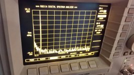
Still wondering what the BIAS is meant to be, but I got quite far by measuring and tuning
Anyway power fets were far from matched, but I adjusted so that lowest voltage over 1/4ohm resistor bunch was 14mV = 56mA
I guess the highest was up to about 200mA then.
Results are pretty impressive for such a garage build. 1W 1kHz 7ohm
Must say I am also impressed by the simplicity of the signal route.
Maybe this is a good design after all!
Attachments
Oh it was in Portuguese. Well if you find the BIAS value please tell me. And also how to adjust the temp protection. I guess I could figure out this much myself too from the text if I had it.
On some forum I found some text in German, but it had to be missing something, as I did not find any mA values.
Sorry if I was unclear in the beginning. My buzamp is the one with two BUZ23 FETs in parallell as in el156s photos
On some forum I found some text in German, but it had to be missing something, as I did not find any mA values.
Sorry if I was unclear in the beginning. My buzamp is the one with two BUZ23 FETs in parallell as in el156s photos
that one was meant to have 100mA per FET; resulting in 200mA per channel.Sorry if I was unclear in the beginning. My buzamp is the one with two BUZ23 FETs in parallell as in el156s photos
- Status
- This old topic is closed. If you want to reopen this topic, contact a moderator using the "Report Post" button.
- Home
- More Vendors...
- Elektor
- Amplifier circuit from Elektor