Hi everyone,
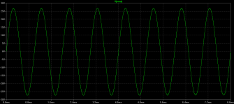
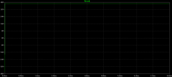
I'm simulating an amplifier based on one of Bob Cordell's designs, but in the simulation, when I use 5, 7 and 13 ohm loads the output stays at 40V, I don't know what is causing this, for 4,6,8 and 16 ohm the output graph is ok, what's happening?
I'm using LTSpice.
Attached examples of the outputs, simulation file and Bob Cordell's models.
Best regards,
Daniel Almeida
Attachments
Well I never used Spice for simulation. I hash it out with pencil, paper, and calculator just like I was trained to do decades ago.
These results don't make sense to me. If an amplifier can drive 4, 8, and 16 ohm loads, but not 5, 7, and 13 ohm loads, then it will never be able to drive a real world speaker. There must be some kind of glitch.
Hopefully someone with Spice simulation experience can clear it up. My opinion is that Spice is wrong in this application.
But the amplifier will work in the real world?
The circuit seems electrically fine.
Best regards,
Daniel Almeida
The circuit seems electrically fine.
Best regards,
Daniel Almeida
Spice does funny things if inadequate accuracy settings are chosen. If you simulate for extended times, the automatically chosen timestep might be too large, causing the simulation output to be garbage.
Rundmaus
EDIT: Looked into your file. I wouldn't trust a simulation starting at time zero. Let it 'run' for 10-20s and start taking data then.
Rundmaus
EDIT: Looked into your file. I wouldn't trust a simulation starting at time zero. Let it 'run' for 10-20s and start taking data then.
Last edited:
you may also want to use the "startup" and "uic" options to see exactly what the circuit will do from power up. let it run for 5-10s like that and you will see any powerup oscillation and the effects of the input/feedback caps charging
This efects could be harmful?
What is the directive directive for startup and uic?
Thanks for your help,
Best regards,
Daniel Almeida
What is the directive directive for startup and uic?
Thanks for your help,
Best regards,
Daniel Almeida
you can invoke startup in the Edit Simulation Command dialog box, under the transient tab, click the box that says:
Start external DC supply voltages at 0V:
That puts the word startup at the end of the .tran statement
Update My Dynaco
Akitika GT-101 Audio Power Amplifier Kit
Start external DC supply voltages at 0V:
That puts the word startup at the end of the .tran statement
Update My Dynaco
Akitika GT-101 Audio Power Amplifier Kit
Here's the helpscreen (F1) on UIC;
UIC
Use Initial Conditions. Normally, a DC operating point analysis is performed before starting the transient analysis. This directive suppresses this initialization. The initial conditions of some circuit elements can be can be specified on an instance-per-instance basis. Uic is not a particularly recommended feature of SPICE. Skipping the DC operating point analysis leads to a nonphysical initial condition. For example, consider a voltage source connected in parallel to a capacitance. The node voltage is taken as zero if not specified. Then, in the first time step, an infinite current is required to charge the capacitor. The simulator cannot find a short enough time step to make the current nonsingular, and a "time step too small convergence fail" message is issued.
Yes those comands after tran also works, but the problem is that I've no op.
If I use .op instead of .tran 8m startup uic it gives me wrong values, with .tran 8m stratup uic the transient is fine, but I have no operation point.
Is this normal?
Best regards,
Daniel Almeida
If I use .op instead of .tran 8m startup uic it gives me wrong values, with .tran 8m stratup uic the transient is fine, but I have no operation point.
Is this normal?
Best regards,
Daniel Almeida
Not sure what your trouble is. I have the files installed, and it sims ok. Which sims are complaining?
The problem is RL = 5 or 7 and 13 ohm, Vout stays at -38V at op.
Best regards and thanks for your concern,
Daniel Almeida
Best regards and thanks for your concern,
Daniel Almeida
OK...I have duplicated the problem.
It's a latchup issue in the simulator, that might actually happen in the real world.
The simulator starts at a bad output voltage, that puts a bad voltage on C3, and pretty well ruins the operation of the input stage, and then everything stays bad. Place back-to-back 1N4148 across C3, which is probably a good idea anyway, and the problem is solved.
Update My Dynaco
Akitika GT-101 Audio Power Amplifier Kit
Right, thank you very much for your help,
So I should put an inverted 1N4148 diode across C3 terminals,
This problem occurs in real life?
Best regards,
Daniel Almeida
So I should put an inverted 1N4148 diode across C3 terminals,
This problem occurs in real life?
Best regards,
Daniel Almeida
Yes, the inverted diode at the terminals of C3 completely solves the problem,
Thank you very much, now the amplifier drives all the possible loads, except less than 2ohm 😉
Best regards,
Daniel Almeida
Thank you very much, now the amplifier drives all the possible loads, except less than 2ohm 😉
Best regards,
Daniel Almeida
That's the interesting question.
The diodes are a good idea, as it prevents too much voltage across the cap under fault conditions. Still, the funny thing is that C3 starts out with about -37 volts across it...that just wouldn't happen in real life unless the positive rail was missing.
Interestingly, if you let it sim for 800 ms, it comes out of the funny state around 700 ms.
More interestingly, I changed Q2's model from the 2N5401C model to a different 2N5401 model on my machine, and the problem went away.
Hmmm...I'll report more if I see something definite.
Dan
I can cut the positive rail with a switch transistor to make a shutdown network?
This seems to work fine in simulation, STK series from Sanyo uses a similar network.
Or this is dangerous?
I can also make a mute network at the input with an analog mux with one or more bits for control, with ground, and the audio signal(s).
Best regards,
Daniel Almeida
This seems to work fine in simulation, STK series from Sanyo uses a similar network.
Or this is dangerous?
I can also make a mute network at the input with an analog mux with one or more bits for control, with ground, and the audio signal(s).
Best regards,
Daniel Almeida
Attachments
It seems ok...I worry a bit about leakage currents that could make Q10 turn on and Q4 pull down. 10 uA of leakage current feeding the base of Q4 pulls the output down to -430 mV. So...you might ask...where does 10 uA of leakage current come from? Maybe it's not a problem.
However...Did you swap D3 D4 with R27?
However...Did you swap D3 D4 with R27?
Yes you're right, I swap D3 and D4 with R27 accidentaly, D3 and D4 are used to polarize the base of Q15, thank you for correcting me.
Best regards,
Daniel Almeida
Best regards,
Daniel Almeida
- Status
- Not open for further replies.
- Home
- Amplifiers
- Solid State
- Amplifier can't drive 5,7 and 13 ohm loads