Note that if the amplifier, in real life, breaks into parasitic oscillation, SPICE sims of the amp won't always show that happening. I found out the hard way.Dear friends.
I build this vintage quasi amplifier in ltspice. I just start using ltspice a few days ago so i wanted to know that how to simulate it. Need advice and tips.
Thanks in advance.

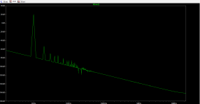
It's a good idea to view the Bode plot for the amp to get a bead on its stability.
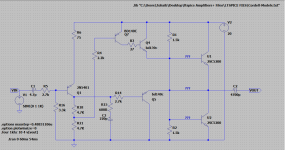
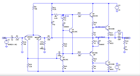
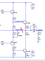
Did you build this amp?You were properly guided by Mr. Steveu. I'd like to provide you with a schematic that might be useful in building the amplifier of your dreams.
View attachment 1243338
How does it sound?
This amp is huge 😳😱 BD140 Ucb max - 80v.
This circuit will be better for a voltage on rails of 100 volts. You can practice on it, draw it in LTspice.
Try feeding an input signal to the model that would ask for an output voltage higher than the specified rail voltage(s). Unless LT spice updated to correct for that, you could swing the output to the high heavens in spite of a small rail voltage.😱 BD140 Ucb max - 80v.
This circuit will be better for a voltage on rails of 100 volts. You can practice on it, draw it in LTspice.
The sound of the amp is quite impressive... sometimes I feel it can bet my Yamaha receiver... hahaha...Did you build this amp?
How does it sound?
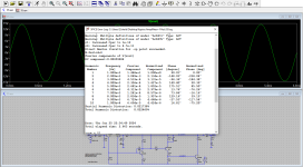
(The circuit from #4) How does that even work? There's no DC path to the base of Q4, so it'll be switched off with only leakage currents flowing I think?Made another amplifier in lt spice but disortion is not getting low.
How to lower the disortion and how to dc off set?
Low distortion usually involves a current-mirror load to the input pair, and an emitter follower added to the VAS, both exemplified in the Doug Self "Blameless Amplifier" design(s).
I'd go for a phase margin of at least 60 degrees as the gain approaches unity at high frequencies.It's a good idea to view the Bode plot for the amp to get a bead on its stability.
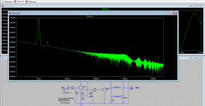
I'm afraid its not working 🙁 You can see that from the output amplitudes. Nothing there really. No amplitude of signal.
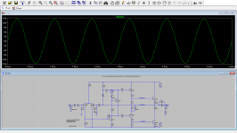
There is a lot wrong with the basic configuration unfortunately. Try this, all with default models. I'll let you tidy it up and add suitable output stage bias.

There is a lot wrong with the basic configuration unfortunately. Try this, all with default models. I'll let you tidy it up and add suitable output stage bias.
Attachments
T
Thanks mooly sir i will try this.I'm afraid its not working 🙁 You can see that from the output amplitudes. Nothing there really. No amplitude of signal.
There is a lot wrong with the basic configuration unfortunately. Try this, all with default models. I'll let you tidy it up and add suitable output stage bias.
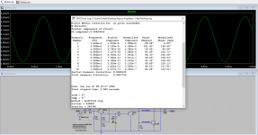
Load the amp with an 8- or 4-Ohm resistor; drive it into clipping; plot V(out)*I(load). Start with plotting V(out) and edit it by right clicking the plot label. Left click and drag to the peak to measure the power trace. The rms power will be half the clipping power. Expect he positive and negative clip to be slightly different. The power may be "negative" if I(load) is backwards, flip the load resistor.
Simulating clipping is also an important step to detect rail sticking and stability problems.
Simulating clipping is also an important step to detect rail sticking and stability problems.
Attachments

Apologies but I'm a bit curious, and you are in the simulation so perhaps it's easy - I was wondering what it would do if that connection was removed 🙂phase margin
The idea is that the driver section uses the feedback loop, but the output followers just chat to the speaker without being pulled about by the feedback loop.
Attachments
The driver Q8 requires current through D3 from the speaker to drive U2. U2 is not a follower and requires feedback from Q8 to find the correct current. What you suggest is possible with a fully complementary output NPN+PNP, but there will be distortion in the "followers" so it's not useful. Perhaps you are thinking about current dumping, but that involves a tricky mix of both stages.
- Home
- Amplifiers
- Solid State
- Amplifier build in LTspice