Schematics and gerber files are in attachments.
It is not the best practice to parallel amplifiers like this, but I went for it anyways just for fun! 🙂
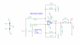
Noise gain is 10 V/V
Signal gain is 20 V/V
It is essential to use 0.1% feedback resistors:
Any thoughts are welcome and appreciated.
It is not the best practice to parallel amplifiers like this, but I went for it anyways just for fun! 🙂
Noise gain is 10 V/V
Signal gain is 20 V/V
It is essential to use 0.1% feedback resistors:
- it will improve CMRR as each LM3886 acts as a difference amp
- it will match the gain for all three ICs - which in turn creates less standing current in output ballast resistors.
Any thoughts are welcome and appreciated.
Attachments

Last edited:

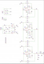
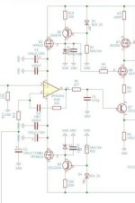
Stability components C12-C17, C9 - C11, and L1 R27 should assure good stability at the gain of 20k/4k = 5 for each of LM3886.LM3886 noise gain = 6 whereas DS says min stable gain = 10?
Gain of the first stage is 1 + 2*1k/1.4k = 2.4287
Total gain = 12.14 and allows for output voltage swing of ~ +/- 34 V - assuming power supply voltage of 36V to 37V should fully utilize those chips.
Overall gain can be configured with only one resistor - R7:
- 2K will give you gain of 10
- 1.8k -> gain of 10.5556
- 1.6k -> gain of 11.25
- 1.5k -> gain of 11.6667
- 1.4k -> gain of 12.1435
- for speakers with 8 ohms each chip will see 8*3 = 24 ohms
- for speakers with 6 ohms each chip will see 6*3 = 18 ohms
- for speakers with 4 ohms each chip will see 4*3 = 12 ohms
- for speakers with 3 ohms each chip will see 2*3 = 6 ohms - not recommended
Last edited:
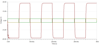
The compensation caps are only needed if you want good performance as the output swings near the supply rails. The LM3886 is perfectly stable mid-rail with a gain of 10 V/V (20 dB).My recommendation would be to go to a gain of say 12 (above the minimum for stability) and do away with all those comp caps.
Things like 100pF across the chip inputs are a brute-force way to ensure stability, they lower the loop gain and increase the distortion.
Tom
Coming back to this post because I am not happy with the sound of my current build that does have cap across chip inputs.My recommendation would be to go to a gain of say 12 (above the minimum for stability) and do away with all those comp caps.
Things like 100pF across the chip inputs are a brute-force way to ensure stability, they lower the loop gain and increase the distortion.
Not sure exactly what it is, but will be diving into trying different measurements and experimentation to hopefully pinpoint the issue.
Maybe after all it does make sense to omit that cap and raise the gain.
Note that THD measurements were excellent, but the amp still does not sound good.
Meaning probably need to measure something else... not sure what yet...
Maybe time delay in the feedback loop?... idk...
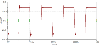
If LM3886 to be configured with gain of less than 10x, feedback lead compensation is needed for stability.
Cap across feedback resistor of 33pF or 47pF will accomplish that.
It will form a low pass filter with a feedback resistor.
It will also help to prevent stray capacitances from inverting pin.
Capacitor across inv and non inverting pins needs to be removed for compensation to work properly.
Cap across feedback resistor of 33pF or 47pF will accomplish that.
It will form a low pass filter with a feedback resistor.
It will also help to prevent stray capacitances from inverting pin.
Capacitor across inv and non inverting pins needs to be removed for compensation to work properly.
Attachments
H
HAYK
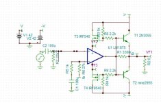
If you need more current using the LM1875, you can get by adding a pair of low cost power transistors and a 0.33 ohm resistor on the output in class C. If higher voltage is needed, add bootstrap mosfets and you get over 70W.
Attachments
looks fun!
how about thd? seems that adding two output transistors can be challenging to get good thd?
what is T2? MNE2955?
how about thd? seems that adding two output transistors can be challenging to get good thd?
what is T2? MNE2955?
H
HAYK
I got confused with 3x3886 and 3x1875.
The distortion without that of the lm which in this case negligible, is for 50W, 0.01% 1khz and 0.2% 20khz. Better output transistors with lower weighing resistor might decrease it. The LM3886 can function with light load of <2A with +/-42V. You don't need to bootstrap.
The distortion without that of the lm which in this case negligible, is for 50W, 0.01% 1khz and 0.2% 20khz. Better output transistors with lower weighing resistor might decrease it. The LM3886 can function with light load of <2A with +/-42V. You don't need to bootstrap.
Attachments
Some time ago I came by this amplifier called Q17. Here is the thread link - https://www.diyaudio.com/community/threads/q17-an-audiophile-approach-to-perfect-sound.374507/
It uses similar power delivery with CCS using MOSFETS. The author claims better sound when using them.
Schematic is attached
It uses similar power delivery with CCS using MOSFETS. The author claims better sound when using them.
Schematic is attached
Attachments
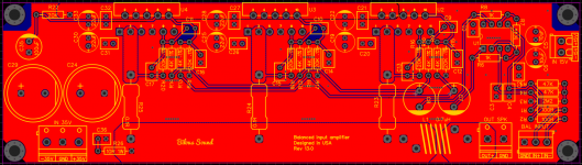
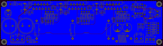
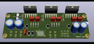
I’m currently working on design that will have three lm3886 with most components in SMD.
I’m also planning to put input buffer on separate PCB for two channels. Probably will add voltage regulators for 15V on the same board. Gain will be adjustable between 21dB, 26dB and 29dB.
As a result I am hoping to get THD+N below 0.001% at 5W and output power 70W/140W into 8/4 ohms loads.
I also test listened my previous builds against Modulus-86 and it did not sound as good at all. I fixed it by modifying compensation and by using film caps in the feedback loop.
Promises to be a fun project.
- Home
- Amplifiers
- Chip Amps
- Amplifier based on 3 x LM3886 in parallel with balanced inputs