There are quite a few threads/articles on this forum and elsewhere regarding stepping down amplified output signals to line level inputs. However, I have an application that is slightly unique (many signals, different step down levels, sound quality required, bass levels important).
The amplified signal is not from a powerful amplifier as it only outputs up to 3W output between 4 ohms and 32 ohms impedance. The input is line level (+4 dBV). My goal is to retain as much sound quality as is reasonable. In my application, there will be 40 signals, so cost is a factor and thus Jensen or equivalent transformers would be prohibitively expensive.
It is my understanding (which is limited) that transformers have the disadvantage of decreasing low frequency output. That is problematic as my application will have significant bass signals and even subsonic signals down to 10 hz (will be routed to tactile transducers).
Given my application requiring sound quality, full bandwidth signal, and cost (many channels), what is a recommended solution (e.g., voltage divider, car audio transformers, etc.)? I am afraid that this may be one of those scenarios where tradeoffs exist (cost vs sq vs signal bandwidth) and one can only have two of three. However, I hopeful the creative minds here may have viable solution for my hobby project.
Are these 40 different signals to be selected individually and you want them to be at the same level when selected? or are you wanting to mix them all together?
My first thought is to use an opamp based virtual earth mixer as that allows each level to be set precisely with one resistor. Each input can be selected individually or they can be mixed. The circuit is very simple, one opamp overall and one resistor per input, value of resistor determines that inputs gain. You might need one further opamp to preserve overall phase.
My first thought is to use an opamp based virtual earth mixer as that allows each level to be set precisely with one resistor. Each input can be selected individually or they can be mixed. The circuit is very simple, one opamp overall and one resistor per input, value of resistor determines that inputs gain. You might need one further opamp to preserve overall phase.
Yes, each of the 40 channels will be selected individually.
The audio routing will be: Source (max 3W@4-32Ohms)>Line level converter?>MOTU +4dBV analog input sound cards (e.g., 24I & 2408MKII)>PC VST Host (various plugin effects applied to each channel)>MOTU soundcard analog outputs>amplifier>speakers/headphones.
The output will be 8 channels total. It will be any combination of the 40 input channels. So some inputs off, some combined together to one output, some outputs only having on input, etc. All if the signal routing from the 40 inputs to the 8 outputs will be done in a PC VST host (Plogue Bidule).
Unfortunately, the source is proprietary and so I have no choice but to step down the audio signal. In other words, I cannot substitute another source.
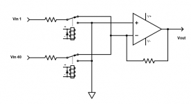
With all of the 40 inputs going to a single mixer IC inverting input, the noise gain will be very high.
For each source you could use a series resistor selected for proper gain, which then goes to a relay.
The relay selects sending that signal line to either audio ground (off), or to the op amp virtual ground (on).
In this manner, only eight lines are connected to the mixer op amp's negative input at one time,
so the noise gain is five times lower than having all 40 lines connected at the same time.
Because of this, the noise floor will be lower, and the audio high frequency bandwidth will be higher.
Attachments
That was the part I didn't quite follow in post #1The audio routing will be: Source (max 3W@4-32Ohms)>Line level converter?>MOTU +4dBV analog input sound cards (e.g., 24I & 2408MKII)>PC VST Host (various plugin effects applied to each channel)>MOTU soundcard analog outputs>amplifier>speakers/headphones.
So you are using the 3W amp as a source and stepping that down to line level. Assuming rms values then if it can deliver 3W into 4 ohms then it is able to output up to 3 volts rms and if it delivers 3 watts into 32 ohms then that is almost 10 volts rms. So you have lots of signal available.
https://www.electronics-notes.com/a...amp/virtual-earth-mixer-summing-amplifier.php
As I'm perhaps a permanent newbie on the electronics side (much more comfortable physically building speaker enclosures), I just realized I may have left out other pertinent information.
All 40 inputs, while providing different audio sounds, will be at the same signal level as the sources are all identical circuits. The MOTU devices are multichannel duplex ADCs/DACs. There are three MOTU duplex sound cards slaved together (one MOTU 24I, two MOTU 2408 MKIIs, slaved together so they appear to the PC as one virtual ADC/DAC).
There will always be a maximum of 8 output signals. These will each have individual analog amplifiers to change the volume.
However, the number of active inputs will vary from day to day. Some days, 20 of the inputs may be used simultaneously, while other days only 15 inputs may be used. So input channels 1, 5 & 8 may be summed into output channel one, input channels 2 & 3 into output channel 2, input channel 4 into output channel 3, etc. The combinations of channels vary frequently, but are not random.
The input signals will not be combined in the analogue stage, but in the digital domain using VST plugins/mixers. So the audio path will be both analogue and digital: 3W amplifier[Analogue]>Line level converter? (if needed)[Analog]>MOTU +4dBV line level input [Analogue]>MOTU ADC [Digital]>Channels mixed/effects applied via VST Host [Digital]>MOTU DAC>MOTU analogue outputs [Analogue]>....
Just providing this update as it may change the previous recommendations. If not, let me know.
Mooly, thank-you for the link! That helped me understand better. Your description of the audio signal path is correct.
Rayma, thank-you for the explanation regarding the summing of noise! I had not thought of that. Do the same concerns exist given channels will be summed in the digital domain, not the analogue circuit? Also, even though the three MOTU ADC/DAC sound cards appear digitally as a single device, do the 40 input signal still share the same ground or are there actually three grounds (one per MOTU device)? The MOTUs share a PCI card, each connected to it by Firewire cables. If there are three grounds, then it may make sense to divide the more frequently used input channels among the three physical devices so the signals are not summed to a single ground, instead of having the most frequently used channels input to the same MOTU ADC. I hope I am understanding this correctly.
BTW, I forgot to mention this project is not theoretical. I already have the entire audio chain connected and working, including the VST plugins, using a cheap Behringer duplex ADC/DAC sound card. However, it is currently only two channel input/output. I am using a cheap transformer for car audio to drop the signal to line level. The challenge is that the low frequencies seem to be cut off (no surprise!) and the sound quality likely can be improved. So now I am ready to improve frequency bandwidth, sound quality, and increasing the input to 40 channels. I have all the MOTU sound cards, but am waiting for cables and adapters to be shipped before they are integrated.
Last edited:
If the channels are summed in the digital domain, the concept of noise gain does not apply.
That is only for an analog op amp with feedback. It's not really about noise per se, but more
about how a real op amp functions in a circuit.
Noise gain is the effective gain referred to the positive input, even if there is no signal applied there.
All the 40 audio lines applied through a resistor R1 to the inverting input are in parallel for noise gain,
so the noise gain is 1 + R2 / 40R1, even though the signal gain for each line is - R2 / R1,
where R2 is the resistor from the output to the inverting input.
So there would be narrower HF bandwidth and a higher noise level.
The grounds are best worked out by trial and error for minimum noise.
Last edited:
That is a relief. I apologize for not providing sufficient info at first. I did not realize the ADC/DAC effect until reading further on the suggested circuits.If the channels are summed in the digital domain, the concept of noise gain does not apply.
This is only for an analog op amp with feedback.
The grounds are best worked out by trial and error for minimum noise.
Given the new information regarding the digital domain, for stepping down the signal to line level, are there differing recommendations on the best approach given the constraints? It would be nice to purchase 40 Jensen transformers, but that is out of the budget.
So 3W @4 Ohms is about 3.5Vrms or +14dBm. The only reason a simple -10bB pad is not the solution is grounding problems.
1. Transformers deal well with grounding problems, and because we do not care about signal efficiency, we can use inexpensive transformers wound for higher impedance to reach lower frequencies. Transformers do need to be loaded to control self-resonance.
2. But it is easier to use balanced inputs capable of handling +14dBm. Some mixers should be able to do that, or with balanced attenuators.
https://www.amazon.com/10db-Balanced-Xlr-Attenuator/dp/B00AZTWD3S
3. If you want a custom DIY solution, a simple op-amp mixer (but not as simple as a summing amp) with balanced inputs would work fine. The only issue is that it will need a power source, and this assumes you understand grounding and RFI.
The biggest issue is the requirement for a 40x8 switching matrix. Is that really necessary? At a minimum, that means 320 DPDT switches. A much more economical design would be 40+ XLR jacks which you use to select the inputs for each of 8 mixers.
And at +4dBm, noise is just not an issue.
PS. 0dbV ~= +2.2dBm
Last edited:
Simplest way to attenuate analog signals is an L pad, which is one series resistor and one shunt resistor.
Determine the smallest resistor value that the source can drive properly, and make the sum
of those two resistors equal to that. Then determine the ratio of the resistors from the attenuation needed.
Determine the smallest resistor value that the source can drive properly, and make the sum
of those two resistors equal to that. Then determine the ratio of the resistors from the attenuation needed.
what is a recommended solution (e.g., voltage divider, car audio transformers, etc.)?
Given the low output impedance perhaps 500 ohm log-law preset pots would make a simple adjustable attenuator array. 500 ohms can
handle 10V or so I think (some reasonable sized cermet presets perhaps). Full bandwidth to DC, simple and low noise.
Not in this case, as the signal is from power amplifier - no need to dissipate 3W in the divider.Determine the smallest resistor value that the source can drive properly, and make the sum
of those two resistors equal to that.
Interesting. Using cheap(er) transformers capable of handling lower frequencies seems a viable solutions. Will have have to try learn more how to do this.1. Transformers deal well with grounding problems, and because we do not care about signal efficiency, we can use inexpensive transformers wound for higher impedance to reach lower frequencies. Transformers do need to be loaded to control self-resonance.
The input channels are mono (which can be balanced), but unfortunately the source units are not pro grade audio, so I am pretty sure the signal would not be balanced. The source is meant to driver very small transducers (speakers). Can +/- speaker wires be used as a balance input signal to the sound cards.But it is easier to use balanced inputs capable of handling +14dBm. Some mixers should be able to do that, or with balanced attenuators.
This is a none issue. I may have communicated poorly, but all of the mixing with be in the digital domain. There are no needs for DPDT switches, except perhaps to isolate sources when not in use.The biggest issue is the requirement for a 40x8 switching matrix. Is that really necessary? At a minimum, that means 320 DPDT switches. A much more economical design would be 40+ XLR jacks which you use to select the inputs for each of 8 mixers.
Interesting idea as well. As all of the 40 sources are exactly the same circuits and thus dBV, could this idea be simplified further? In other words, I'm not sure "adjustable" attenuation is even needed since the source level (output) and the line level (input) is known. It seems a fixed value attenuation should be sufficient. But my knowledge level in the circuit universe is limited...Given the low output impedance perhaps 500 ohm log-law preset pots would make a simple adjustable attenuator array.
This idea seems like a really simple solution, particularly for scaling to 40 channels. Ultimately, once the circuit design is refined for one channel, I'd like to make a custom PCB with 40 channels so there is not a spaghetti mess of wires.Simplest way to attenuate analog signals is an L pad, which is one series resistor and one shunt resistor.
- Home
- Design & Build
- Parts
- Amplified signal output to line level inputs