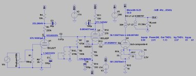
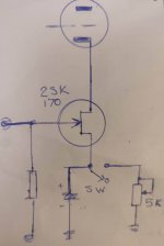
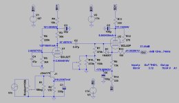
I'm very happy with your cooperation. Since I had no reference for choosing the FET (the markings were removed), I tried what I had available—a 2N3819—as it practically didn't amplify anything. I then looked for a FET that's fairly common in audio equipment, which is why I chose the 2SK170. By the way, you simulated a 60 mV input, but my measurements show a higher signal.
The signal applied in these two screenshots is the blue trace. In the first one,on the left we see the signal applied to the cathode of the triode (yellow trace) without distortion at maximum volume. In the second screenshot, on the right, we see the signal at the output of the pentode's cathode before being applied to the final 2A3 stage.
The remaining issue is the crackling noise due to the variation in cathode bias.


AND
By measuring, observing, and rechecking... I realized that by placing the capacitor in series with the center of the potentiometer, the FET's bias changes. This was the reason for the distorted waveform.
Basically, with the new FETs, without the capacitor, we find the source of the FET connected to the cathode at 3.7V and the drain at 0V. With the capacitor in place, we measure 9.7V at the FET's source and a floating voltage of just a few dozen millivolts at the drain.
At this point, I don’t often use FETs, but since I found two different FETs on the two channels—where only the final part of the markings is visible (one ending in B004 and the other in B107)—do you think they are installed correctly?
They are mounted on a socket, as seen in the photo. I’m concerned that someone may have installed them rotated by 180 degrees.
Thanks for the help you’re giving me!
I almost forgot—the switch mounted on the PCB internally enables or bypasses the 5K potentiometer in parallel with the 330 µF capacitor placed between the FET's gate and ground.
Toggling it on or off does not cause any bias variation, nor does it produce any noticeable change.
The signal applied in these two screenshots is the blue trace. In the first one,on the left we see the signal applied to the cathode of the triode (yellow trace) without distortion at maximum volume. In the second screenshot, on the right, we see the signal at the output of the pentode's cathode before being applied to the final 2A3 stage.
The remaining issue is the crackling noise due to the variation in cathode bias.
AND
By measuring, observing, and rechecking... I realized that by placing the capacitor in series with the center of the potentiometer, the FET's bias changes. This was the reason for the distorted waveform.
Basically, with the new FETs, without the capacitor, we find the source of the FET connected to the cathode at 3.7V and the drain at 0V. With the capacitor in place, we measure 9.7V at the FET's source and a floating voltage of just a few dozen millivolts at the drain.
At this point, I don’t often use FETs, but since I found two different FETs on the two channels—where only the final part of the markings is visible (one ending in B004 and the other in B107)—do you think they are installed correctly?
They are mounted on a socket, as seen in the photo. I’m concerned that someone may have installed them rotated by 180 degrees.
Thanks for the help you’re giving me!
I almost forgot—the switch mounted on the PCB internally enables or bypasses the 5K potentiometer in parallel with the 330 µF capacitor placed between the FET's gate and ground.
Toggling it on or off does not cause any bias variation, nor does it produce any noticeable change.
spippolone:
I almost forgot—the switch mounted on the PCB internally enables or bypasses the 5K potentiometer in parallel with the 330 µF capacitor placed between the FET's gate and ground.Toggling it on or off does not cause any bias variation, nor does it produce any noticeable change.}
how ?The amazing thing is that.......
We have very good experts in this forum who have written articles about cascode many times, but they are not willing to help. Your amplifier problem need experienced engineers . This topic is a very good test for skills in tube circuits.
There is another option, I suppose: Assume that the circuit is unworkable, and should be made less complicated and easier to support, using the parts you have and the bulk of the circuit. Wouldn't it be possible to just send the input to the grid of the ECL82 triode and skip the FET altogether?
@OldHector are right.
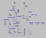
Triode part of ECL/PCL82 has enough gain to drive 2A3, even via cathode follower.
Sample:

Triode part of ECL/PCL82 has enough gain to drive 2A3, even via cathode follower.
Sample:

One of the best single ended tube amp.... that I made ... the input was cascode. So should try to get it right.
Dear Hooman I think the you can understand even if I draw a little badly in attach also the picure of impedance filter all the amplifier.


hi ...Thank you. It's perfect. Sorry, I didn't notice for a few days.I was actually waiting.🙂
- Home
- Amplifiers
- Tubes / Valves
- Ampli PCL82 + 2A3


