In my never ending search for a better B+ delay I've decided to try Ampterite delay relays. I think making a SS device in a shape of a tube is at least funny, so I'd go for it. (Hope someone makes an octal 4558 soon!)
There are many threads mentioning the subject but (singing) I still haven't found what I'm looking for.
The Amperite's datasheet doesn't give the heaters' current ratings and somewhere I've read that it's adviced to turn the relay off after it closes to save the heater. The deatasheet keeps silence about that.
And I'd like to see some schems - although it seems obvious I'm sure there are bugs I'm not aware of (like that above mentioned thing with turning it of after it closes).
Amperite tube-shaped Delay Relays datasheet
Who uses them?
I think all the old Tektronix tube scopes like the 535 and 545 used them. Seemed to work just fine, as my Teks have been going strong since the '70s.
I have used one once in a prototype..It worked great.
You have to leave the heater connected,or else the contacts will open up again..
It's basically a bi-metal switch (like a thermostat),with an attached heater.
You have to leave the heater connected,or else the contacts will open up again..
It's basically a bi-metal switch (like a thermostat),with an attached heater.
The Amperite datasheet does give the heater rating, indirectly: 2 watts. So ~320mA at 6.3V.
A comon scheme is to use a relay in addition to the delay relay to de-activate the delay relay heater after power-up. This allows the delay relay to cool so that if you turn the power off then back on, you get the full power-up delay.
I found a thread on a different forum with a schematic:
http://www.diytube.com/phpBB2/viewtopic.php?t=1268&sid=36a2df9b96ca7e3fc6d790598f7e3af2
Pete
30-40 years ago, the Aperite datasheets DID suggest using a latching relay which also removes power to the delay tube heater. Four advantages I can think of:
1) saves heater life
2) prevents contact chatter, as it latches on first contact
3) lets relay cool for next operation
4) relay can have greater voltage / current rating than delay tube
I like the Potter & Brumfield T92 relay - it's rated for 380 VAC and 30A, easy to mount and not too expensive.
1) saves heater life
2) prevents contact chatter, as it latches on first contact
3) lets relay cool for next operation
4) relay can have greater voltage / current rating than delay tube
I like the Potter & Brumfield T92 relay - it's rated for 380 VAC and 30A, easy to mount and not too expensive.
A comon scheme is to use a relay in addition to the delay relay to de-activate the delay relay heater after power-up. This allows the delay relay to cool so that if you turn the power off then back on, you get the full power-up delay.
On the flip side, the audio tubes will be warmer as well, in a turn-off turn-on circumstance when compared to a cold start. So the delay shouldn't have to be as long.
I used an Amperite in my Aikido for quite some time. I used one of the old schematics from Amperite that only had the delay tube powered while it was timing. Basically:
1. The power is applied to the Amperite
2. When the timer trips, it switches an Omron DPDT relay to which the PSU is connected.
3. When the Omron tripped, it switched on the PSU, the other Omron contacts took switched to open and took the Amperite out of circuit.
I can look-up the schematic for you and send it.
Charlie
Gents,
I did use that schematic that Tom McNally suggested on DIYtube to pre-heat before I switched on my 83 Rectifier. Works well - just make sure you have a nice quiet relay or you'll get some hum.
-Steve
I did use that schematic that Tom McNally suggested on DIYtube to pre-heat before I switched on my 83 Rectifier. Works well - just make sure you have a nice quiet relay or you'll get some hum.
-Steve
relay + relay + relay
Thanks a lot for the tips, and how come I've missed the 2W heater rating? I was probably thinking it's a plate dissipation 😎
Now isn't that weird that you have a delay relay activating another relay? If you have a relay already in a circuit you can hook it up with some - 555 and save space. Although any DIP-8 looks bad inside a tube chassis. That's why I'd ask for an octal 555 as well.
At some point I've thought I'm going to order a couple of delay relays and stick them in without additional relays in a standby switch position.
But some posters say you cannot wire them to HV. For example here's something by coresta :
So the second relay is a must?
Thanks a lot for the tips, and how come I've missed the 2W heater rating? I was probably thinking it's a plate dissipation 😎
Now isn't that weird that you have a delay relay activating another relay? If you have a relay already in a circuit you can hook it up with some - 555 and save space. Although any DIP-8 looks bad inside a tube chassis. That's why I'd ask for an octal 555 as well.
At some point I've thought I'm going to order a couple of delay relays and stick them in without additional relays in a standby switch position.
But some posters say you cannot wire them to HV. For example here's something by coresta :
Hi ! I'm using XT90As from the former Thomson-CSF in my OTLs . These could be subs of 6NO90 if they do exist ! But caution :
Don't use these to switch directly HV !! As TEKTRONIX did , they turn a low voltage relay on to avoid arcing . 😉
So the second relay is a must?
ampeg SVT 69
I've found the Ampeg SVT scheme with delay relay tube. The heater is mains AC and it turns on the HT transformer's primary. No additional relays.
I know this amp is famous for it's fireworks.
I've found the Ampeg SVT scheme with delay relay tube. The heater is mains AC and it turns on the HT transformer's primary. No additional relays.
I know this amp is famous for it's fireworks.
How high is the insulation voltage ? In fact , the delaying tubes are not high speed switches ... they do not work as toggle sw. Have a look at the contacts when switching on  the associated relay(s) may have a very higher speed and , as previously said, allow you to disconnect the heaters 😉 the ampeg svt was a big tubes eater huh ? 😉
the associated relay(s) may have a very higher speed and , as previously said, allow you to disconnect the heaters 😉 the ampeg svt was a big tubes eater huh ? 😉Did you note something curious on the Ampeg schematic?
For the plate supply they have two electrolytic caps in series, along with its ballast resistors. This is standard procedure to provide a much higher voltage rating.
However, the top section is 100 uf, while the bottom section is 40 + 70 = 110 uF. Why would they do that?
For the plate supply they have two electrolytic caps in series, along with its ballast resistors. This is standard procedure to provide a much higher voltage rating.
However, the top section is 100 uf, while the bottom section is 40 + 70 = 110 uF. Why would they do that?
schematics
This is not the original Ampeg sheet, it's drawn by Joe Piazza who was repairing the amp and documented what was in that specific head. So it's possible they were out of 100uF 's when this particular amp was made - or it was repaired or whatever.
fernando_g said:Did you note something curious on the Ampeg schematic?
For the plate supply they have two electrolytic caps in series, along with its ballast resistors. This is standard procedure to provide a much higher voltage rating.
However, the top section is 100 uf, while the bottom section is 40 + 70 = 110 uF. Why would they do that?
This is not the original Ampeg sheet, it's drawn by Joe Piazza who was repairing the amp and documented what was in that specific head. So it's possible they were out of 100uF 's when this particular amp was made - or it was repaired or whatever.
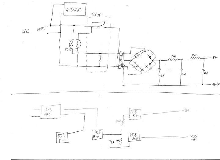
This is the schematic that I used. Look at the TDR (Amperite) and the relay (Omron). The Amperite was mounted above the chassis while the Omron was hot-glued inside the chassis and was not visible. The Omron was from Radioshack and cost less than $10.
On switch-on, the heaters are fed with 6.3V. The Amperite gets 115V via the "normally-closed" relay of the Omron. When the Amperite trips, the Omron is then switched, which makes the "normally-open" contacts closed (powering the B+) and the "normally-closed" contacts become "open" which removes the Amperite from the circuit. In the event of a power outage, the Omron causes an immediate reset.
Charlie
- Status
- Not open for further replies.
- Home
- Amplifiers
- Tubes / Valves
- Amperite delay relays