"When you have -55 on the rails, do you also have that on the negative speaker terminal and the RCA shields?"
No that is with the neg of the meter connected to the speaker minus.
No that is with the neg of the meter connected to the speaker minus.
What if you place the black probe on the primary ground terminal?
On the point where you had the ground of the LV supply connected?
On the positive speaker terminal?
On the point where you had the ground of the LV supply connected?
On the positive speaker terminal?
"When you have -55 on the rails, do you also have that on the negative speaker terminal and the RCA shields"
No. That's with the meter negative referenced to speaker negative.
No. That's with the meter negative referenced to speaker negative.
Okay, back from camping. Put the amp on the bench. Hooked it up to make sure everything is still the same. With no driver board, driver transistors or outputs installed the amp pulls current when I put a rectifier in it. Power supply runs fine with out the rectifier. Other than caps, what else in the rails can cause this?
Went over the circuit board with Magnifier and bright light. No solder bridges. Rectifier checked good. Put a new one in anyway. Still pulls current. I can lift the positive or negative on the rectifier and it stills pulls current.
How much current?
Do you read a short across the caps?
With no rectifier, what's the DC voltage on the secondary ground? (black probe on primary ground)
Do you read a short across the caps?
With no rectifier, what's the DC voltage on the secondary ground? (black probe on primary ground)
Insert a 120v incandescent bulb in series with the input terminal of the rectifier (you can also try the other terminals) to see if you get any voltage across anything on the secondary.
Thanks Perry for taking the time to help with this. It was my own stupid mistake. I guess I was gun shy and not wanting to burn stuff up. I wasn't leaving it turned on long enough for the caps to charge. As soon as I saw the current jump I turned it off. I waited a little longer this time and the current fell to 5 amps. I will now try to answer your previous questions. Thanks for being patient with me as I learn.
Okay, got the low voltage power supply to work. What the meter said was common to speaker ground wasn't. I put ground to the speaker negative and the LV works. I have +/- 18 volts on the rails.
I rebuilt the drive module. Replaced the TL072, LM211, LM2903 (I used a LM393) and both 21844's. Being very careful not to over heat them. I have good low side drive. Put a 9V battery on the high side. Negative to pin 11. Positive to pin 13. No high side drive. Removed the battery and put 2 outputs in just to test. I get a high pitched squall out to the speaker. Doesn't pull current. Lamp doesn't glow. Any ideas?
I rebuilt the drive module. Replaced the TL072, LM211, LM2903 (I used a LM393) and both 21844's. Being very careful not to over heat them. I have good low side drive. Put a 9V battery on the high side. Negative to pin 11. Positive to pin 13. No high side drive. Removed the battery and put 2 outputs in just to test. I get a high pitched squall out to the speaker. Doesn't pull current. Lamp doesn't glow. Any ideas?
Did you try more than one IC? I've had at least one that I damaged when I installed it and the high-side drive was absent.
For ground, you can't trust the meter because it will read through various transformer winding which will look like a direct short. Using the negative speaker terminal was a good idea.
For ground, you can't trust the meter because it will read through various transformer winding which will look like a direct short. Using the negative speaker terminal was a good idea.
Both driver chips are missing the high side drive. I guess I could have knocked out both. I did ohm check them after installed. I use a fine bead of solder paste to install them. Takes very little time to flow. Then I clean them up. I'll change them again.
Use the terminals on the IC. That diagram is useful but the references are random. You earlier stated that you had the battery across 11 and 13 which is correct.
What's the DC voltage on pin 2 of the 21844? (black on negative rail)
What's the amplitude of the drive signal on pin 1?
What's the DC voltage on pin 2 of the 21844? (black on negative rail)
What's the amplitude of the drive signal on pin 1?
Attached the 9V battery to pins 11 & 13.
DC voltage on Pin 2 is 5.16volts.
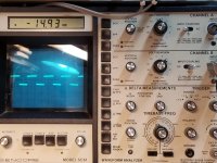
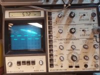
Attached pics of the input signal pin1.
DC voltage on Pin 2 is 5.16volts.
Attached pics of the input signal pin1.
Attachments
Last edited:
For all but the high-side terminals, you place the black probe on the negative rail to measure voltage.
For the waveform, you need to use DC coupling. The voltage is low enough to allow that. Make a note of the negative rail voltage or post a photo of the scope trace on the negative rail.
For the waveform, you need to use DC coupling. The voltage is low enough to allow that. Make a note of the negative rail voltage or post a photo of the scope trace on the negative rail.
- Home
- General Interest
- Car Audio
- Ampere Audio 8.0